TOPIC 1: WAVES
Introduction to Waves
The Concept of Wave
Explain the concept of a wave
A wave is a disturbance that travels through a medium from one location to another location.
Consider a slinky wave as an example of a wave. When the slinky is stretched from end to end and is held at rest, it assumes a natural position known as the equilibrium or rest position.
The coils of the slinky naturally assume this position, spaced equally far apart. To introduce a wave into the slinky, the first particle is displaced or moved from its equilibrium or rest position. The particle might be moved upwards or downwards, forwards or backwards; but once moved, it is returned to its original equilibrium or rest position.
The act of moving the first coil of the slinky in a given direction and then returning it to its equilibrium position creates a disturbancein the slinky. We can then observe this disturbance moving through the slinky from one end to the other. If the first coil of the slinky is given a single back-and-forth vibration, then we call the observed motion of the disturbance through the slinky a slinky pulse.
A pulse is a single disturbance moving through a medium from one location to another location.
However, if the first coil of the slinky is continuously and periodically vibrated in a back-and-forth manner, we would observe a repeating disturbance moving within the slinky that endures over some prolonged period of time. The repeating and periodic disturbance that moves through a medium from one location to another is referred to as a wave.
A medium is a substance or material that carries the wave.
You have perhaps heard of the phrase news media. The news media refers to the various institutions (newspaper offices, television stations, radio stations, etc.) within our society that carry the news from one location to another. The news moves through the media.
The wave medium is not the wave and it doesn't make the wave; it merely carries or transports the wave from its source to other locations.
In the case of our slinky wave, the medium through that the wave travels is the slinky coils. In the case of a water wave in the ocean, the medium through which the wave travels is the ocean water. In the case of a sound wave moving from the church choir to the pews, the medium through which the sound wave travels is the air in the room.
The Terms Wave Length, Frequency and Velocity of a Wave
Explain the terms wave length, frequency and velocity of a wave
Consider the transverse wave below:
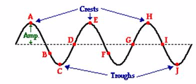
- A transverse wave is a wave in which the particles of the medium are displaced in a direction perpendicular to the direction of energy transport.
- The crest of a wave is the point on the medium that exhibits the maximum amount of positive or upward displacement from the rest position.
- The trough of a wave is the point on the medium that exhibits the maximum amount of negative or downward displacement from the rest position.
- The amplitude of a wave refers to the maximum amount of displacement of a particle on the medium from its rest position. In a sense, the amplitude is the distance from rest to crest. Similarly, the amplitude can be measured from the rest position to the trough position.
- The wavelength of a wave is simply the length of one complete wave cycle. If you were to trace your finger across the wave in the diagram above, you would notice that your finger repeats its path. A wave is a repeating pattern. It repeats itself in a periodic and regular fashion over both time and space. And the length of one such spatial repetition (known as a wave cycle) is the wavelength. The wavelength can be measured as the distance from crest to crest or from trough to trough. In fact, the wavelength of a wave can be measured as the distance from a point on a wave to the corresponding point on the next cycle of the wave.
- A longitudinal wave is a wave in which the particles of the medium are displaced in a direction parallel to the direction of energy transport. A longitudinal wave can be created in a slinky if the slinky is stretched out horizontally and the end coil is vibrated back-and-forth in a horizontal direction.
- A compression is a point on a medium through which a longitudinal wave is traveling that has the maximum density. A region where the coils are spread apart, thus maximizing the distance between coils, is known as a rarefaction.
- A rarefaction is a point on a medium through which a longitudinal wave is traveling that has the minimum density. Points A, C and E on the diagram above represent compressions and points B, D, and F represent rarefactions.
- The frequency, (f) of a wave refers to how often the particles of the medium vibrate when a wave passes through the medium. Given this definition, it is reasonable that the quantity frequencywould have units of cycles/second, waves/second, vibrations/second, or something/second. Another unit for frequency is the Hertz (abbreviated Hz) where 1 Hz is equivalent to 1 cycle/second. If a coil of slinky makes 2 vibrational cycles in one second, then the frequency is 2 Hz.
- Period, (T) refers to the time that it takes to do something. When an event occurs repeatedly, then we say that the event is periodic and refer to the time for the event to repeat itself as the period. The period of a wave is the time for a particle on a medium to make one complete vibrational cycle. Period, being a time, is measured in units of time such as seconds, hours, days or years. The period of orbit for the Earth around the Sun is approximately 365 days; it takes 365 days for the Earth to complete a cycle.
- The speed of an object refers to how fast an object is moving and is usually expressed as the distance traveled per time of travel. In the case of a wave, the speed is the distance traveled by a given point on the wave (such as a crest) in a given interval of time.The SI unit of speed is m/s.
Wave equation
The wave equation shows the relationship between speed, wavelength and frequency of a wave.
The diagrams below show several "snapshots" of the production of a wave within a rope. The motion of the disturbance along the medium after every one-fourth of a period is depicted. Observe that in the time it takes from the first to the last snapshot, the hand has made one complete back-and-forth motion.
A period has elapsed. Observe that during this same amount of time, the leading edge of the disturbance has moved a distance equal to one complete wavelength. So in a time of one period, the wave has moved a distance of one wavelength. Combining this information with the equation for speed (speed = distance/time), it can be said that the speed of a wave is also the wavelength/period.
Since the period is the reciprocal of the frequency, the expression 1/f can be substituted into the above equation for period. Rearranging the equation yields a new equation of the form:
Speed = Wavelength • Frequency.The above equation is known as the wave equation. It states the mathematical relationship between the speed (v) of a wave and its wavelength (λ) and frequency (f). Using the symbols v, λ, and f, the equation can be rewritten asv = f • λ
Types of Waves
Identify types of waves
Previously we classified the waves by considering the movement of the particles. And now you’re going to find out the 2 types of waves according to the media of propagation.
- Mechanical Waves
- Electromagnetic Waves
Mechanical Waves
Mechanical waves are also called elastic waves as their propagation depends on the elastic properties of the medium through which the waves pass
Mechanical waves are divided into three categories: Transverse waves, longitudinal waves, and surface waves. In transverse waves, the medium moves perpendicular to the wave direction, and in longitudinal waves, the medium moves parallel to the wave direction.
In surface waves, both transverse and longitudinal waves mix in a single medium. In very simple words, an electronic wave is that which travels in a vacuum, and a mechanical wave is that which needs some medium for traveling.
Examples of mechanical waves are Sound waves, Water waves , Ocean waves, Earth quake waves, Seismic waves
Electromagnetic Waves
Electromagnetic waves are waves that have no medium to travel whereas mechanical waves need a medium for its transmission. Examples of electromagnetic waves include light and radio signals.
The following are the differences between mechanical and electromagnetic waves.
- Electromagnetic waves travel in a vacuum whereas mechanical waves do not.
- The mechanical waves need a medium like water, air, or anything for it to travel.
- While an electromagnetic wave is called just a disturbance, a mechanical wave is considered a periodic disturbance.
- Behaviour of WavesReflection, Refraction, Diffraction and Interference of WavesExplain Reflection, refraction, diffraction and interference of wavesAll waves behave in certain characteristic ways. They can undergo:
- Reflection
- Refraction
- Diffraction
- Interference
These basic properties define the behaviour of a wave – anything that reflects, refracts, diffracts and interferes is labelled a wave.ReflectionReflection is the change in direction of a wavefront at an interface between two different media so that the wavefront returns into the medium from which it originated. Common examples include the reflection of light, sound and water waves.The law of reflectionIf the reflecting surface is very smooth, the reflection of light that occurs is called specular or regular reflection. The laws of reflection are as follows:- The incident ray, the reflected ray and the normal to the reflection surface at the point of the incidence lie in the same plane.
- The angle which the incident ray makes with the normal is equal to the angle which the reflected ray makes to the same normal.
- The reflected ray and the incident ray are on the opposite sides of the normal.
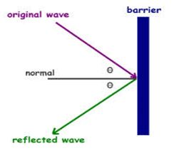 Characteristics of Reflection of waves:
- It obeys the Law of Reflection.
- The wavelength, λ of the reflected wave is the same as that of the incident waves.
- The frequency,fof the reflected waves is the same as that of the incident waves.
- Therefore the speed, v of the reflected waves is the same as that of the incident waves.
Types of reflection:- Specular: Smooth surfaces direct reflected light at opposite angle.
- Diffused: Rough surfaces scatter light in all directions.
- Spread: Some surfaces have a combination texture and smooth surface (varnish overcoat on paper, white label on white bottle).
Ripple TankA ripple tank is a shallow glass tank of water used in schools and colleges to demonstrate the basic properties of waves. It is a specialized form of a wave tank. The ripple tank is usually illuminated from above, so that the light shines through the water.Some small ripple tanks fit onto the top of an overhead projector, i.e. they are illuminated from below. The ripples on the water show up as shadows on the screen underneath the tank. All the basic properties of waves, including reflection, refraction, interference and diffraction, can be demonstrated.Ripples may be generated by a piece of wood that is suspended above the tank on elastic bands so that it is just touching the surface. Screwed to wood is a motor that has an off centre weight attached to the axle. As the axle rotates the motor wobbles, shaking the wood and generating ripples.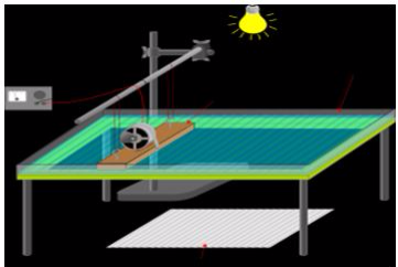 RefractionRefraction is the change in direction of propagation of a wave due to a change in its transmission medium.The phenomenon is explained by the conservation of energy and conservation of momentum. Due to change of medium, the phase velocity of the wave is changed but its frequency remains constant. This is most commonly observed when a wave passes from one medium to another at any angle other than 0° from the normal.Refraction of light is the most commonly observed phenomenon, but any type of wave can refract when it interacts with a medium, for example when sound waves pass from one medium into another or when water waves move into water of a different depth.
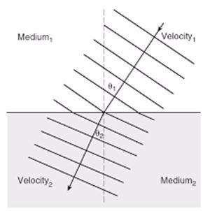 Snell’s lawRefraction is described by Snell's law, which states that: “For a given pair of media and a wave with a single frequency, the ratio of the sines of the angle of incidence θ1 and angle of refraction θ2 is equivalent to the ratio of phase velocities (v1 / v2) in the two media, or equivalently, to the opposite ratio of the indices of refraction (n2 / n1)”
 The refractive index or index of refractionn of an optical medium is a dimensionless number that describes how light, or any other radiation, propagates through that medium.Refraction of a light ray.The refractive index determines how much light is bent, or refracted, when entering a material. This is the historically first use of refractive indices and is described by Snell's law of refraction, n1 sin θ1 = n2 sin θ2, where θ1 and θ2 are the angles of incidence and refraction, respectively, of a ray crossing the interface between two media with refractive indices n1 and n2.The refractive indices also determine the amount of light that is reflected when reaching the interface, as well as the critical angle for total internal reflection and Brewster's angle.InterferenceInterference is a phenomenon in which two waves superpose to form a resultant wave of greater or lower amplitude.Interference usually refers to the interaction of waves that are correlated or coherent with each other, either because they come from the same source or because they have the same or nearly the same frequency.Interference effects can be observed with all types of waves, for example, light, radio, acoustic, surface water waves or matter waves.Constructive InterferenceConstructive interference is a type of interference that occurs at any location along the medium where the two interfering waves have a displacement in the same direction.In this case, both waves have an upward displacement; consequently, the medium has an upward displacement that is greater than the displacement of the two interfering pulses. Constructive interference is observed at any location where the two interfering waves are displaced upward. But it is also observed when both interfering waves are displaced downward.This is shown in the diagram below for two downward displaced pulses.
 -In this case, a sine pulse with a maximum displacement of -1 unit (negative means a downward displacement) interferes with a sine pulse with a maximum displacement of -1 unit. These two pulses are drawn in red and blue. The resulting shape of the medium is a sine pulse with a maximum displacement of -2 units. <!-- [if !supportLineBreakNewLine]--> <!--[endif]-->Destructive InterferenceDestructive interference is a type of interference that occurs at any location along the medium where the two interfering waves have a displacement in the opposite direction.For instance, when a sine pulse with a maximum displacement of +1 unit meets a sine pulse with a maximum displacement of -1 unit, destructive interference occurs.DiffractionDiffraction refers to a change in direction of waves as they pass through an opening or around a barrier in their path.
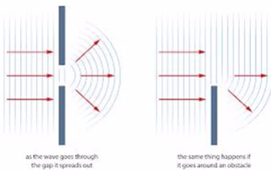 In classical physics, the diffraction phenomenon is described as the interference of waves according to the Huygens–Fresnel principle. These characteristic behaviors are exhibited when a wave encounters an obstacle or a slit that is comparable in size to its wavelength. Similar effects occur when a light wave travels through a medium with a varying refractive index, or when a sound wave travels through a medium with varying acoustic impedance.Diffraction occurs with all waves, including sound waves, water waves, and electromagnetic waves such as visible light, X-rays and radio waves. Diffraction arises because of the way in which waves propagate; this is described by the Huygens–Fresnel principle and the principle of superposition of waves.The propagation of a wave can be visualized by considering every particle of the transmitted medium on a wavefront as a point source for a secondary spherical wave. The wave displacement at any subsequent point is the sum of these secondary waves.When waves are put together, their sum is determined by the relative phases as well as the amplitudes of the individual waves so that the summed amplitude of the waves can have any value between zero and the sum of the individual amplitudes.A long slit of infinitesimal width which is illuminated by light diffracts the light into a series of circular waves and the wavefront which emerges from the slit is a cylindrical wave of uniform intensity.A slit which is wider than a wavelength produces interference effects in the space downstream of the slit. These can be explained by assuming that the slit behaves as though it has a large number of point sources spaced evenly across the width of the slit
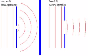 Diffraction of water waves is observed in a harbor as waves bend around small boats and are found to disturb the water behind them. Diffraction of sound waves is commonly observed; we notice sound diffracting around corners, allowing us to hear others who are speaking to us from adjacent rooms.Diffraction is observed of light waves but only when the waves encounter obstacles with extremely small wavelengths (such as particles suspended in our atmosphere).The Application of Reflection, Refraction, Diffraction and Interference of Waves in Daily LifeMention the application of reflection, refraction, diffraction and interference of waves in daily lifeApplication of reflection of waves
- The phenomenon of the reflection of sound is used to determine the distance between the two objects, for example depth of seabed, depth of cave or width of a valley. The type of sound used must be ultrasound.
- Sonar (Sound Navigation and Ranging). Sonar is used to detect underwater objects (corals / fishes) or to determine the depth of the water by means of an echo. Sonar equipment emits a high frequency sound signal which is reflected by the object in the water. The reflected sound wave is received by the sonar receiver. The time taken for the echo to return is used to determine the distance of the object below the water surface. Sonar waves of high frequency is used because itpossessesmore energy, high penetration power and can travel further through water.
- Reflection of light waves is used in the design of mirrors.
- Detection of cracks in metals.
- Determination of frequency of A.C’s.
Applications of Refraction- Refraction has many applications in optics and technology. A lens uses refraction to form an image of an object for many different purposes, such as magnification.
- A prism uses refraction to form a spectrum of colors from an incident beam of light.
- Refraction also plays an important role in the formation of a mirage and other optical illusions.
Applications of interference of waves- Interference is applied when creating holograms. A hologram is a photograph of an interference pattern which is able to produce a three-dimensional image when suitably illuminated.
- Destructive interference is used in noise reduction systems such as earphones.The system capture sound from the environment and use computer technology to produce a second sound wave,which leads to reduction in the loudness of the noise.
- Concert halls and auditorium are usually designed in such a way to reduce the amount of destructive interference. Usually, the walls and ceiling made in such a way that they absorb rather than reflect sound.
Application of wave diffraction- Diffraction Grating: A diffraction grating is an optical device that consists of not one but many thousands of apertures. Spectra produced by diffraction gratings are extremely useful in applications from studying the structure of atoms and molecules to investigating the composition of stars.
- X-ray diffraction: X rays are light waves that have very short wavelengths. When they irradiate a solid, crystal material they are diffracted by the atoms in the crystal.x-ray diffraction utilises an instrument called a diffractometer to produce diffraction patterns that can be compared with those of known crystals to determine the structure of new materials.
- Holography: Holography is the science and practice of making holograms. Normally, a hologram is a photographic recording of a light field, rather than of an image formed by a lens, and it is used to display a fully three-dimensional image of the holographed subject, which is seen without the aid of special glasses or other intermediate optics. An illuminating laser beam is diffracted at specific angles, in accordance with Bragg's law, on the surfaces of the hologram, making it possible for an observer to see a three-dimensional image.
The Behaviour of WavesDemonstrate the behaviour of wavesActivity 1Demonstrate the behaviour of wavesBehaviour of Waves are reflection, refraction, diffraction and interference of Waves. All waves behave in certain characteristic ways. They can undergo: Reflection, Refraction, Diffraction and Interference.These basic properties define the behaviour of a wave – anything that reflects, refracts, diffracts and interferes is labelled as a wave. - Propagation of WavesThe Propagation of Mechanical WavesDescribe the propagation of mechanical wavesMechanical waves can be divided into three main categories according to the ways in which they travel, known aspropagation. The three propagation types are:
- Atransverse waveis one that vibrates at 90 degrees to the direction the wave is moving. For example, if you hold a Slinky between two hands and shake it up and down, you'll get a wave that moves along the Slinky, but the vibrations will still be up and down. Underwater waves are also transverse.
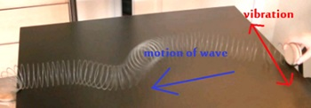
Transverse wave- Alongitudinal waveis one in which the vibrations are parallel to the direction the wave is moving. That's like sending a pulse along the length of a Slinky, pushing it lengthwise. Instead of peaks and troughs, longitudinal waves havecompressions(areas where the Slinky is bunched together), andrarefactions(areas where the Slinky is spread apart). Another example of a longitudinal wave is a sound wave. Although you can't see air molecules, if you could, you would notice that sound involves air molecules hitting each other, thereby producing areas with high densities of molecules (compressions) and areas with low densities of molecules (rarefactions).
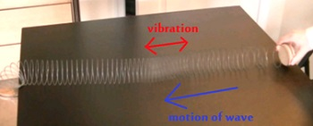
Longitudinal wave- Last of all, asurface waveis a wave that travels along the boundary between two materials. For example the kind of water wave you most often see--along the top of water--is an example of a surface wave. Surface waves move in similar ways to transverse waves but are a bit more complicated in their behavior.
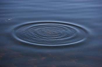
Surface waveIn the case of an earthquake, you get a mixture of all three types of waves. The initial earthquake (called the primary wave) is longitudinal, but the aftershock that comes later (called the secondary wave) is transverse. Extra surface waves are also created.The Propagation of Electromagnetic WavesExplain the propagation of electromagnetic wavesElectromagnetic waves are transverse waves only. Velocity of all electromagnetic waves is equal to the velocity of light which is 300,000,000 m/s (3x10exp8). Electromagnetic waves do not need medium for their transmission. Electromagnetic waves are arranged in special arrangement known as electromagnetic spectrum according to the increase in their frequencies or decrease in their wavelengths.The Relationship between Frequency, Speed and Wavelength of a WaveDetermine the relationship between frequency, speed and wavelength of a waveFrequency (f) of a wave is inversely proportional to its wavelength (l). Speed (V) of a wave is constant. That is, f=V/l. That is Speed of a wave can be expressed as a product of frequency and wavelength. That is, V = f X l Speed of a wave is expressed in meters per second (m/s). Period (T) of a wave is a time taken by a wave to complete one oscillation. Frequency is a reciprocal of the Period.Mathematically it can be shown as:v = f • λwhere- v =speed of a wave
- λ =wavelength
- f = frequency
The Refractive Index of a MediumDetermine the refractive index of a mediumRefractive index(n) is a ratio of the velocity (Va) of a wave in air to its velocity in a medium (Vm). n=Va/Vm. Refractive index can also be obtained as a ratio of the sine of angle of incidence (Sin i) to the sine of angle of refraction (Sin r). The speed of the wave depends on the medium through which it travels. Changing the medium changes the speed. Absolute refractive index=V in vacuum/V.Refractive index of a material is a measure of the change in speed of light as it passes from a vacuum (or air as an approximation) into the material. In the equation above,v1is the speed of light in a vacuum. The bigger the refractive index the slower the light travels in that material - i.e. the smallerv2is.Example 1Light of frequency 4.6 × 10¹⁴Hz travels at a speed of 1.24 × 10⁸ms-1in diamond.Calculate the refractive index of diamond for this colour of light.Solutionvdiamond= 1.24 × 10⁸ms-1c= 3.0 × 10⁸ms-1(from data sheet)
 Refractive index of diamond for this colour of light = 2.42
 - Sound WavesSource of Sound WaveIdentify source of sound wavesSound is oscillation in pressure, stress, particle displacement, particle velocity, etc., propagated in a medium with internal forces (e.g., elastic or viscous), or the superposition of such propagated oscillation.The sources of sound
- vibrating solids.
- rapid expansion or compression (explosions and implosions).
- Smooth (laminar) air flow around blunt obstacles may result in the formation of vortices (the plural of vortex) that snap off or shed with a characteristic frequency. This process is called vortex shedding and is another means by which sound waves are formed. This is how a whistle or flute produces sound. Also the aeolian harp effect of singing power lines and fluttering venetian blinds.
The Concept of AudibilityExplain the concept of audibility rangeAudibility range the range of frequencies that can be heard by humans or other animals, though it can also refer to the range of levels.The human range is commonly given as 20 to 20,000Hz, though there is considerable variation between individuals, especially at high frequencies, and a gradual loss of sensitivity to higher frequencies with age is considered normalSensitivity also varies with frequency, as shown by equal-loudness contours. Routine investigation for hearing loss usually involves an audiogram which shows threshold levels relative to a normal. Several animal species are able to hear frequencies well beyond the human hearing range. Some dolphins and bats, for example, can hear frequencies up to 100kHz.Several animal species are able to hear frequencies well beyond the human hearing range. Some dolphins and bats, for example, can hear frequencies up to 100kHz.The Perception of HearingDescribe the perception of hearingA basic measure of hearing is afforded by an audiogram: a graph of the minimum discernible sound level at various frequencies throughout an organism's nominal hearing range.Behavioural hearing tests or physiological tests can be used to find hearing thresholds of humans and other animals. For humans, the test involves tones being presented at a specific frequencies (pitch) and intensities (loudness). When the subject hears the sound, he or she indicates it by raising a hand or pressing a button. The lowest intensity they can hear is recorded.The human earThe ear is the organ that detects sound. It not only receives sound, but also aids in balance and body position. The ear is part of the auditory system.Often the entire organ is considered the ear, though it may also be considered just the visible portion. In most mammals, the visible ear is a flap of tissue that is also called the pinna (or auricle in humans) and is the first of many steps in hearing.Vertebrates have a pair of ears placed somewhat symmetrically on opposite sides of the head. This arrangement aids in the ability to localize sound sources.The human ear is divided into three parts:The outer earThe outer ear comprises the pinna (auricle), which is made of a convoluted plate of flexible cartilage that extends as a nearly closed tube one-third of the way down the ear canal. This outer third, which is about eight millimetres (one-third of an inch) long, has small hairs that point outwards to form a line of defence against small animals creeping in. The roots of the hairs produce oils and these mix with the secretions from nearby sweat-like glands to form the basis of wax.The deep two-thirds of the ear canal (16 millimetres/two-thirds of an inch long) has a bony wall lined with thin and rather fragile skin which is devoid of glands. At the far end of the ear canal and stretched across it is the eardrum (tympanic membrane), which forms the boundary between the outer and middle ears.The middle ear (Tympanum)The eardrum is a circle of thin skin about eight to nine millimetres (one-third of an inch) in diameter. Despite its name, it is not flat like the skin of a drum, but is slightly conical with the curved sides sloping inwards. The eardrum has three layers.The inner ear (Labyrinth)The inner ear is probably the most remarkably intricate piece of the body. It makes hearing possible by converting sound into electrical impulses that then travel along the hearing nerve (the acoustic nerve or auditory nerve) to the brain. The inner ear also plays a major role in balance. The balance portions of the inner ear (vestibular labyrinth) can detect acceleration of the head in any direction whether in a straight line (linear) or twisting and turning (angular). The electrical signals that arise in response to head movement pass along the balance nerve (vestibular nerve), which in due course joins with the hearing nerve to form a single bundle (statoacoustic, vestibulo-acoustic or eighth nerve, nerve VIII) which then enters the brain.The portion of the inner ear that actually hears is the cochlea. This is a hollow coiled tube set in the very dense bone called the bony labyrinth (part of the petrous [rocklike] temporal bone). This tube is filled with fluid, which is much the same as general body fluid (lymph) and that which surrounds the brain (cerebrospinal fluid – CSF). This inner-ear fluid is called perilymph. Inside the perilymph is another coiled triangular-shaped tube called the cochlear duct (scala media), which contains the all-important ‘hair cells’ – these convert sound into electricity. These hair cells are arranged in two groups that follow the coils of the cochlear duct and spiral upwards from base to apex. There is a single row of inner hair cells (IHCs), which lie closer to the core of the cochlea (modiolus), and three or four rows of outer hair cells (OHCs), which are further away. In a healthy young human ear there are about 3,500 IHCs and about 12,000 OHCs. Each hair cell has a cluster of small rigid hairs (stereocilia), which project from the thicker upper surface of the cell into the special fluid that fills the cochlear duct. This fluid is called endolymph and is remarkable in that it has a strongly positive electrical charge associated with it – about 80 millivolts – and is rich in potassium, a metallic element.The hair cells in their rows are grouped together with their supporting cells in the organ of Corti. This is a small ridge that sits on a thin, very flexible membrane called the basilar membrane. The basilar membrane forms the floor of the triangular cochlear duct. The sloping roof is another very thin membrane (Reissner’s membrane) and the side wall is a thickened region rich in blood vessels (the stria vascularis). This structure is responsible for maintaining the composition of the rather unusual and very important endolymph.Adjacent to the base of the hair cells are the nerves that carry impulses to the brain (the afferent nerves). At least 90 per cent of these nerves come from the inner hair cells, despite their smaller number. Each inner hair cell has about 10 nerve endings attached to it and there are, therefore, about 30,000 nerve fibres in the acoustic nerve.The hearing nerves travel inwards, along with the balance and facial nerves, through a canal in the inner part of the skull (variously called the internal auditory meatus [IAM], internal auditory canal [IAC] or porus acousticus) to reach the brain stem. This part of the brain deals with lots of automatic functions such as pulse, blood pressure, general alertness, balance, and so on.About half of the hearing nerves from each ear cross over to the other side of the brain stem and then, on both sides, the nerves pass up the brain stem through the midbrain, eventually to reach ‘consciousness’ in what is called the cortex of the brain. For hearing, this conscious region is located in the temporal lobe portion of the brain, which lies on each side of the head just above the ear.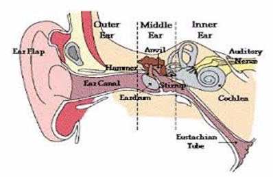 The Concept of Echo and ReverberationExplain the concept of echo and reverberationEchoAn echo occurs when asound wave is reflected and hence arrives to the listener after some time delay after the direct sound.When we are in a empty space surrounded by mountains and we shout loudly, we see that faint sound resembling the original sound coming back after some delay of time. This perception of the reflected wave is nothing but the echo. This is experienced in remote places, in rooms that are big and empty, in caves, buildingsEcho is derived from the Greek word which means Sound.The echo is produced due to hitting of the sound waves with the obstacles which makes the sound to reflect back
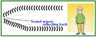 Application of Echo:Measuring distanceBy knowing the speed of sound and measuring the time it takes to hear the echo, you can calculate the distance of the object.A sonar device sends out a sound and automatically calculates the distance of an object. Submarines use sonar to find objects under the water, including other submarines. The "ping" sound heard in a submarine comes from the sonar device sending out a sound wave under water.Fishermen also use sonar to find schools of fish. Since this is an electronic device, the time it takes for the wave to return can be much less than the 0.1 second required to hear an echo. For example, if the speed of sound in water is 1500 m/s and the fisherman's sonar device detects an echo in 0.02s, the distance of the object under water will bed = v x t = 1500 m/s x 0.02s = 30 m (back and forth).That may mean a school of fish are 15 meters away. Sonar and radar work on the same principle. Sonar uses sound waves, while radar uses electromagnetic waves.VelocityWhen a wave bounces off a moving object, the frequency of the sound changes, according to the relative velocity of the object. (Velocity is the measurement of speed and direction). If the object is moving toward you, the frequency or pitch of the sound gets higher. When it is moving away, the pitch gets lower. The faster the object is moving, the greater the change in frequency or pitch. This is called the Doppler Effect.You have probably experienced the Doppler Effect when you heard how the sound of an ambulance siren changes pitch as it passes by. The Doppler Effect can be used to measure the velocity of an object by comparing the frequency of the sound sent out to the frequency of the sound reflected by in the echo. A sonar device is usually used to calculate the velocity of the object.Note: Doppler radar works on a similar principle to measure the speed of storms in weather prediction, except that it uses echoes from electromagnetic waves.Bats can find mothsBats use echoes to find good tasting moths, while flying around at night. The bat sends a sharp click or chirping sound and then hears and processes any echoes off other objects in the area. Bats have large ears that are very sensitive to sounds in certain wavelengthsReverberationReverberations are the collection of reflected sounds from the surfaces in an enclosure like an auditorium. It is a desirable property of auditoriums to the extent that it helps to overcome the inverse square law drop off of sound intensity in the enclosure.However, if it is excessive, it makes the sounds run together with loss of articulation - the sound becomes muddy, garbled.
 A reverberation is the same as echo but the distance here is less.The distance between the source of the sound and the obstacle by which it is reflected is less in Reverberation.Here, in reverberation the time delay is less than 0.1 second.The reflected wave reaches the observer in less than 0.1 second. Now as the delay in time is less than the original sound is still in memory, the delay between perception of sound and the original sound is very-very less.Question Time 1How is an Echo Different from the reverberation?Echo is when long distances are considered and reverberation is when short distances are considered. Echo is due to the reflection of sound wave by obstacles or end points like wall etc. But Reverberation is due to the collection of reflection sounds from the surface which is enclosed completely.The Speed of Sound in AirDetermine the speed of sound in airSound can travel in air (gases), liquids and in solids. Sound is a mechanical wave hence can not travel in vacuum. The speed of sound in air is approximately 340 m/s. The speed of sound in air changes with temperature. As the temperature increase the speed of sound also increases. Sound travel faster in solids than in liquids and air.
Musical Sound
The Concept of a Musical SoundExplain the concept of a musical soundMusic is organised sound which has some pattern. Music uses certain frequencies or combinations of frequencies called the musical scale to produce sounds that are generally appealing to the human ear.Noise on the other hand, is random and without structure. Any and all frequencies might occur and their combination is often not appealing to the ear.Factors Affecting Loudness, Pitch and Quality of Musical SoundIdentify factors affecting loudness, pitch and quality of a musical soundThe musical sounds produced by different musical instruments have distinct properties that are used to describe them. These include loudness, pitch and timbre:- Loudness:loudness is the intensity of the sound which is the perceptual property. It is determined by the amplitude of sound wave and the number of auditory nerves activated by sound wave. Amplitude is a physical property determined by how much air pressure in a compression or rarefaction deviates from normal air pressure. The larger the amplitude the louder the sound.
- Pitch is an auditory sensation in which a listener assigns musical tones to relative positions on a musical scale based on the frequency of sound wave vibration. Frequency is an objective, scientific concept, whereas pitch is subjective. Sound waves themselves do not have pitch. It takes a human brain to map the internal quality of pitch.-Pitches are usually quantified as frequencies in cycles per second, or hertz.
- Timbre is the tone quality of sound produced by an instrument. It is referred to as sound quality or sound colour and it is a perceptual property. What makes a particular musical sound different from another, even when they have the same pitch and loudness.
Different Musical InstrumentsIdentify the different musical instrumentsMusical instrument are the device constructed or modified for the purpose of making music. They are categorizied into three categories:- Wind Instruments:This class of musical instruments requires you to blow into a specific wind instrument by following an order to ensure that the sound that you desire is produced. The instruments can be expected to work depending on the principles of frequencies, sound waves, acoustics, resonance and harmonics. The pitch of the produced sound when you start blowing the instrument is actually dependent on the length of the air column through which the waves of the sounds vibrate.Some of the most popular wind instruments are piccolo, flute, clarinet, shakuhachi, bassoon, oboe, accordion, English horn, harmonica, saxophone, pianica, bagpie and shehnai.
- Percussion Instruments:These instruments require you to strike the surface of the instrument to generate vibrations to produce your desired note. Percussion instruments can actually be divided into two types. The first type includes tuned instrumentsthat are known to produce a definite pitch or a series of different pitches. Some examples of the tuned percussion instruments include xylophone, vibraphone, marimba, tubular bells and timpani or kettle drum. The second type of percussion instruments is the indefinite pitch. Its examples include triangle, castanets, rattle, cymbals, tambourine, anvil and gong.
- String Instruments: These are composed of those instruments that work based on sound wave vibrations produced by strings. The pitch that can be produced by these instruments is dependent on the length of air column and the type and thickness of strings used.Among the most popular string instruments are guitar, viola, violin, cello, mandolin, harp, double bass and banjo.
The Terms Stationary Wave, Nodes and AntinodesExplain the terms stationary wave, nodes and antinodesStationary waveIs a wave in a medium in which each point on the axis of the wave has an associated constant amplitudeThis phenomenon can occur because the medium is moving in the opposite direction to the wave, or it can arise in a stationary medium as a result of interference between two waves traveling in opposite directions.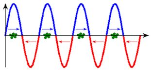 The most common cause of standing waves is the phenomenon of resonance, in which standing waves occur inside a resonator due to interference between waves reflected back and forth at the resonator's resonant frequency.For waves of equal amplitude traveling in opposing directions, there is on averageno net propagation of energy.Traveling waves have high points called crests and low points called troughs (in the transverse case) or compressed points called compressions and stretched points called rarefactions (in the longitudinal case) that travel through the medium.Standing waves don't go anywhere, but they do have regions where the disturbance of the wave is quite small, almost zero. These locations are called nodes. There are also regions where the disturbance is quite intense, greater than anywhere else in the medium, called antinodes.
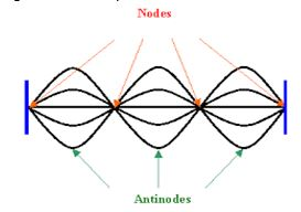 NodesThe locations at which the amplitude is minimum are called nodes.AntinodesThe locations where the amplitude is maximum are called antinodes.The Frequency of a Musical NoteDetermine the frequency of a musical noteThe frequency of a musical note is affected by length of vibrating string and the velocity of the waves. Velocity of the waves depends on the tension on the string and the linear mass density. The linear mass density is the mass per unit length. The frequency of a music note depends on the length, mass per unit length and the tension.The Difference between the Fundamental Note and OvertonesDistinguish between the fundamental note and overtonesFundamental NoteFundamental note is the lowest resonant frequency of a vibrating object. Most vibrating objects have more than one resonant frequency and those used in musical instruments typically vibrate at harmonics of the fundamental.A harmonic is defined as an integer (whole number),n multiple of the fundamental frequency. Vibrating strings, open cylindrical air columns, and conical air columns will vibrate at all harmonics of the fundamental.
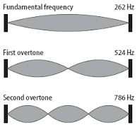 OvernoteAn overtone is any frequency higher than the fundamental frequency of a sound. Using the model of Fourier analysis, the fundamental and the overtones together are called partials.Harmonics, or more precisely, harmonic partials, are partials whose frequencies are integer multiples of the fundamental (including the fundamental which is 1 times itself). These overlapping terms are variously used when discussing the acoustic behavior of musical instruments.There are integer multiples of a certain frequency (fundamental), that are called harmonics, partial tones (partials) or overtones.It is important to note that the term 'overtones' does not include the fundamental frequency. The first overtone is therefore already the second harmonic or the second partial. The term overtone should never be mixed with the other terms, as the counting is unequal.The term harmonic has a precise meaning - that of an integer (whole number) multiple of the fundamental frequency of a vibrating object.The Concept of Resonance as Applied to SoundExplain the concept of resonance as applied to soundResonance is a phenomenon that occurs when a given system is driven by another vibrating system or external force to oscillate with greater amplitude at a specific preferential frequency.Frequencies at which the response amplitude is a relative maximum are known as the system's resonant frequencies, or resonance frequencies.At resonant frequencies, small periodic driving forces have the ability to produce large amplitude oscillations. This is because the system stores vibrational energy. Resonance occurs when a system is able to store and easily transfer energy between two or more different storage modes (such as kinetic energy and potential energy in the case of a pendulum).However, there are some losses from cycle to cycle, called damping. When damping is small, the resonant frequency is approximately equal to the natural frequency of the system, which is a frequency of unforced vibrations. Some systems have multiple, distinct, resonant frequencies.Resonance in Closed Ended PipesA closed ended instrument has one end closed off, and the other end open. An example would be an instrument like some organ pipes (although in some designs they are open), or a flute.Although you blow in through the mouth piece of a flute, the opening you’re blowing into isn’t at the end of the pipe, it’s along the side of the flute. The end of the pipe is closed off near the mouth piece. Remember that it is actually air that is doing the vibrating as a wave here.
- The air at the closed end of the pipe must be a node (not moving), since the air is not free to move there and must be able to be reflected back.
- There must also be an antinode where the opening is, since that is where there is maximum movement of the air.
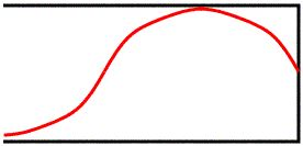
- The simplest, smallest wave that I can possibly fit in a closed end pipe is shown in Figure below.
- Notice how even though it has been flipped left-to-right and it looks squished and stretched a bit to fit, this is still ¼ of a wavelength.
- Since this is the smallest stable piece of a wave I can fit in this pipe, this is the Fundamental, or 1st Harmonic.
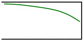 Since the length of the tube is the same as the length of the ¼ wavelength I know that the length of this tube is ¼ of a wavelength… this leads to our first formula: L = ¼ λ
- “L” is the length of the tube in meters. On it’s own this formula really doesn’t help us much.
- Instead, we have to solve this formula for λ and then combine it with the formula v=fλ to get a more useful formula:
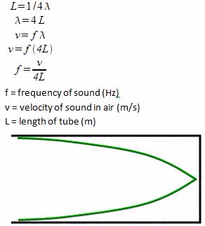 When the wave reaches the closed end it’s going to be reflected as an inverted wave (going from air to whatever the pipe is made of is a pretty big change so this is what we would expect). It would look like Figure above.This does not change the length of the wave in our formula, since we are only seeing the reflection of the wave that already exists in the pipe.What does the next harmonic look like? It’s the 3rd Harmonic.
- I know this name might seem a little confusing (I’m the first to agree with you!) but because of the actual notes produced and the way the waves fit in, musicians refer to the next step up in a closed end pipe instrument as the 3rd harmonic… there is no such thing as a 2nd harmonic for closed end pipes.
- In fact, all of the harmonics in closed end pipes are going to be odd numbers.
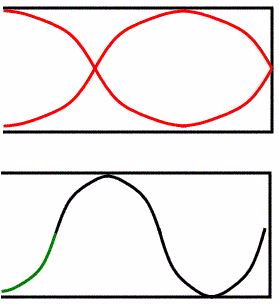
 Remember that we have to have an antinode at the opening (where the air is moving) and a node at the closed end (where the air can’t move). That means for the 3rd harmonic we get something like Figure above. This is ¾ of a wavelength fit into the tube, so the length of the tube is… L = ¾ λThis is the third harmonic of the closed end pipe. The formula for the frequency of the note we will hear is…
 Do you notice a pattern forming in the formulas? Hopefully, because for both open and closed end pipes, we will only give you the formulas for the fundamentals lengths. You need to remember how to get the rest.If we drew in the reflection of the third harmonic it would look like Figure below.
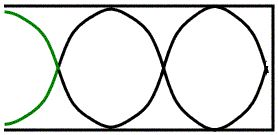
 One more to make sure you see the pattern. The 5th Harmonic (fig. above)There is one full wavelength in there (4/4) plus an extra ¼ of a wavelength for a total of 5/4. The length of the pipe is… L = 5/4 λ And the note produced by the 5th Harmonic is found using the formula…f = 5v/4LFigure below shows the reflection of a 5thHarmonic for a closed end pipe.
 Open End PipesAn open ended instrument has both ends open to the air. An example would be an instrument like a trumpet. You blow in through one end and the sound comes out the other end of the pipe.
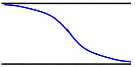
Fundamental- The fundamental (first harmonic) for an open end pipe needs to be an antinode at both ends, since the air can move at both ends.
- That’s why the smallest wave we can fit in is shown in Figure 11.
- This looks different than the ½ wavelength that I showed you in Figure 3, but it is still half of a full wavelength.
- That means the length of the tube and frequency formulas are…L = ½ λ
f = v/2L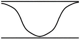
2nd HarmonicThe next note we can play is the 2ndharmonic.- Yep, open end pipes have a 2ndharmonic… they can have any number harmonic they want, odd or even.
- Again, it kind of looks weird, but trace it out and you’ll see that there is exactly one wavelength here.
- The length and frequency formulas are…L = 2/2 λ, f= 2v/2L
I’m not going to show you what the 3rdharmonic looks like. Instead, try drawing it yourself and see what you get.As a hint to help you, the formulas for the length and frequency are…L = 3/2 λ, f = 3v/2LA Simple Musical InstrumentConstruct a simple musical instrumentA musical instrument is a device constructed for making music. There are three categories of musical instruments: string, percussion and wind instruments. The note of a musical instrument depends on five parameters: pitch, frequency, intensity, loudness and quality of a music note. Pitch of a note is its position in the musical scale and depends on the frequency of the vibration of the wave.Activity 2Construct a simple musical instrument
ElectroMagnetic Spectrum
The Concept of ElectroMagnetic SpectrumExplain the concept of the electroMagnetic spectrumThe electromagnetic spectrum is the range of all possible frequencies of electromagnetic radiation.The "electromagnetic spectrum" of an object has a different meaning, and is instead the characteristic distribution of electromagnetic radiation emitted or absorbed by that particular objectThe electromagnetic spectrum extends from below the low frequencies used for modern radio communication to gamma radiation at the short-wavelength (high-frequency) end, thereby covering wavelengths from thousands of kilometers down to a fraction of the size of an atom. The limit for long wavelengths is the size of the universe itself, while it is thought that the short wavelength limit is in the vicinity of the Planck length.Properties of electromagnetic spectrum- It is continuous i.e each band merges into the next and there are no gaps in the frequencies. The different kinds of radiation gradually change from one to another as their properties also gradually change.
- In some case, there is an overlap in the range of wavelength. This is because sometimes the name given to the wave(radiation) is determined by the source and not the wavelength(or frequency) for example x-rays and γ -rays.
The Main Bands of the Electro Magnetic SpectrumIdentify the main bands of the electroMagnetic spectrumRadio wavesRadio waves are a type of electromagnetic radiation with the longest wavelengths in the electromagnetic spectrum. Radio waves have frequencies from 300GHz to as low as 3kHz, and corresponding wavelengths ranging from 1 millimeter (0.039in) to 100 kilometers (62mi).Like all other electromagnetic waves, they travel at the speed of light. Naturally occurring radio waves are made by lightning, or by astronomical objects. Artificially generated radio waves are used for fixed and mobile radio communication, broadcasting, radar and other navigation systems, communications satellites, computer networks and innumerable other applications.Radio waves are generated by radio transmitters and received by radio receivers.Sources of radio waves- alternating electric currents flowing in antennae
- oscillators
- planets, comets, stars and galaxies
MicrowavesMicrowaves have a short wavelength of between 10⁻⁴m to about 0.1.Sources- Are produced by oscillation of charges in special antennae mounted on dishes.
- Magnetrons.
Infrared waves.They have the frequency 0f between 10 and 10 Hz. They lie between the visible light and microwaves. They have the heating effect.Sources: Vibration of atoms and molecules due to their thermal energy. All hot bodies emit infrared radiations.Visible light.Is the narrow range of EW frequencies to which human eyes are sensitive.Detection of Infra-red, Visible and Ultra-violet RaysDetect infra-red, visible and ultra-violet raysInfrared wavesInfrared radiation is invisible to the human eye. However any nocturnal animal can “see” infrared radiations. We can sense infrared radiations as heat. Devices used to detect infrared radiations include black bulb thermometers, photographic films, thermistors and phototransistors.Visible lightWe see things because they either emit visible light or because they reflect visible light from another source.Ultraviolet light.Ultraviolet is light is detected by Photographic films; Fluorescent materials
Application of ElectroMagnetic Wave in daily lifeThe Application of MicroWaves, Radio-Waves, Gamma Rays and X-raysIdentify the application of microWaves, radio-Waves, Infra-red, gamma rays and x-raysRadio waves- Fixed and mobile radio communication, broadcasting, radar and other navigation systems, communications satellites, computer networks and innumerable other applications.
- Astronomers use large radio telescopes to collect and study radio waves from distant stars and galaxies. This helps them to determine composition, structure and motion of the celestial bodies.
Microwaves- In cooking
- Radar systems
- Long distance communication
Gamma rays- Medical application the same as x-rays
- In agriculture
X-rays- X-ray photography
- Diagnosis and treatment of cancer
The Importance of ElectroMagnetic Waves in Agriculture and ClimateExplain the importance of electroMagnetic waves in agriculture and climateElectromagnetic radiations are very useful in agriculture and climate as they support photosynthesis, the main source of oxygen in the atmosphere. Gamma rays are used for pest control by sterilising male pests with gamma radiation then releasing them into the wild, as is done to control tsetse flies. Gamma rays are used to obtain disease-resistant plants. Ultraviolet can purify water and air.- TOPIC 2: ELECTROMAGNETISM
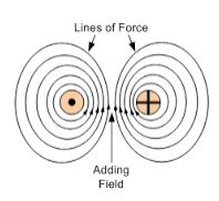
Magnetic Fields due to a Current-carrying ConductorHow Electric Current Produce a Magnetic FieldExplain how electric current produces a magnetic fieldElectromagnetism is the effect produced by the interaction of an electric current with a magnetic field. The interaction can result in a force causing the conductor carrying the current.If, on the other hand, a force is applied to a conductor (with no current) in a magnetic field the resulting movement can result in a current being noticed in the conductor.When the switch is closed an electric current flows through the conductor. The electric current generates magnetic field around the conductor. This will cause a deflection on the compass needle. The magnetic field around a current-carrying conductor can be shown by means of magnetic field lines.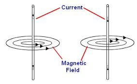 The Pattern of the Magnetic Field Lines around a Straight ConductorIdentify the pattern of the magnetic field lines around a straight conductorThe magnetic field pattern is usually given in a plan view. In the plan view, the conductor is represented by a circle. A dot in circle shows that the current is coming out of the plane. A cross the circle shows that the current is moving into the plane.
 The strength of the magnetic field on the magnitude of the electric current. The higher the current, the stronger the magnetic field, and therefore the greater the deflection. The strength of the magnetic field decreases as you move further from the conductor. There will be less deflection as the compass is drawn from the current-carrying conductor.
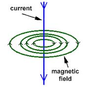 The Direction of Magnetic Field around a Current-Carrying ConductorDetermine the direction of magnetic field around a current-carrying conductorThe direction of the field is determined by applying two rules, these are:
- Right-hand Grip Rule
- Maxwell’s cork screw rule
Right-hand Grip RuleThe Right-hand Grip Rule can be applied to a straight conductor or a solenoid-carrying an electric current. For a straight conductor, the Right-hand Grip Rule can be stated as:“Imagine the wire carrying the current is gripped by the right hand with the thumb pointing in the direction of the conventional current (from positive to negative), the fingers will curl around the wire pointing in the direction of the magnetic field.”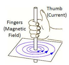 For a solenoid, the Right-hand Grip Rule states that:“When you wrap your right hand around a solenoid with your fingers pointing in the direction of convectional current, your thumb point in the direction of the magnetic North pole.”A solenoid is a long coil containing a large number of close turns of illustrated copper wire.Maxwell’s –Right –hand screw rule states that:“If a right-hand screw advances in the direction of the current, then the direction of rotation of the screw represents the direction of the magnetic field due to the current.”
 The Presence and Direction of a Force on a Current carrying Conductor in a Magnetic FieldDetermine the presence and direction of a force on a current carrying Conductor in a magnetic fieldThe direction of the force on a current-carrying conductor in a magnetic field can be determined using Fleming’s Left –Hand Rule.Fleming’s Left –Hand Rule states that:“If you hold the index finger, the middle finger and the thumb of your left hand mutually perpendicular to each other so that the index finger points in the direction of the magnetic field and the middle finger points in the direction of current in the conductor, then the thumb will point in the direction of the force acting on the conductor.”
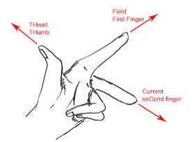 The Direction of Force due to two Current carrying Conductors when the Current Flowing in the Same or Opposite DirectionDetermine the direction of force due to two current '82air-carrying conductors when the current flowing in the same or opposite directionIf two current-carrying conductors are placed side by side close to one another, the currents in the conductors will interact with the magnetic fields produced by the two conductors. A force may result depending on the direction of the two currents.When the currents are flowing in opposite directions, the conductors repel one another. When the currents are flowing in the same direction, the conductors attract one another, the conductors attract each other.When the currents flow in the same direction, the magnetic field between the conductors cancel out, thus reducing the net field. However, on the outside, the magnetic fields add up, thus increasing the net field. Therefore, the magnetic field is weaker between the conductors that on the outside. The resultant force pushes the conductor towards each other.When the currents are in the opposite directions, the fields between the conductors add up, while they cancel out on the outside. The field between them is stronger than on the outside. The resultant force is toward the outside of each conductor, hence repulsion.
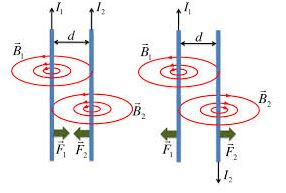
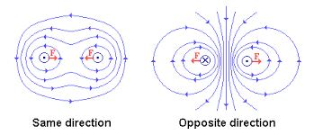
ElectroMagnetic InductionThe Concept of Electromagnetic InductionExplain the concept of electroMagnetic inductionElectromagnetic Induction is the production of e. m. f whenever there is a change in the magnetic flux linking a conductor”. The e. m. f produced is called induced e. m. f and the resulting current induced current.The Laws of ElectroMagnetic InductionState the laws of electroMagnetic inductionLenz’s LawThis explains the direction of the induced e. m. f and it states that: “The direction of the induced e. m. f is such that the resulting induced current flows in such a direction that it opposes the change that causes it.”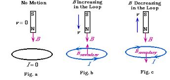 Faraday’s Law.It relates the magnitude of induced e. m. f and the rate of change of the magnetic flux linking the conductor. The magnitude of the induced e. m. f depends on:
- the strength of the magnetic field.
- the rate of change of the magnetic flux(speed of motion)
- the area of the conductor that is in the magnetic field.
Faraday’s law states that: “The e. m. f induced in the conductor in a magnetic field is proportional to the rate of change of magnetic flux linking the conductor.”The Concepts of Self and Mutual InductionExplain the concepts of self and mutual inductionWhen the current flowing through a conductor varies it creates a varying magnetic field that cuts across the conductor itself.This results to self-induced e. m .f in the conductor that is opposite in direction to the original e. m. f. This voltage, usually referred to as back e. m .f, tends to limit or reverse the original current.If the original current is increasing, then the induced current subtracts from it and then measured current is smaller than it would be if no self-induced magnetic field was produced in the conductor. If original current is decreasing, then the original current adds to it and the measured current is greater than it would be if self-induced magnetic field was produced in the conductor. This process is called self-induction since the changing current creates a back e. m. f in itself.Consider a coil of wire wrapped around a cardboard tube. When the coil is connected to a battery a current flows in the coil producing a magnetic field as shown below.If the current in the coil begins to increase, the magnetic flux increases. This induces an e. m. f that opposes the battery resulting in a back current that impedes the increase in current. If the current in the coil decreases, the magnetic flux decreases. This induces an e. m .f that adds to the battery resulting in an induced current that impedes the decrease in current.If we place two coils near each other, a varying current in one coil will induce a current in the other. This is called mutual induction. The coil with a changing current is referred to as the primary coil while that in which a current is induced is the secondary coil.The a.m. induced in the secondary coil is proportional to the rate of change of the current in the primary coil.The Mode of Action of Induction CoilDescribe the mode of action of induction coilIs an electrical device consisting of two coils, the primary coil and the secondary coil, wound one over the other on an iron core.It is used to produce high-voltage alternating current from low-voltage direct current. The primary coil is made up of tens or hundreds of turns of coarse wire while the secondary coil consists of thousands of turns of fine wire. The secondary coil is wound on top of the primary coil.Mode of actionAn induction coil produces high voltage in its secondary coil by electromagnetic induction. The direct current in the primary is switched on and off by a make-and-break mechanism. This produces change in current and magnetic field which is necessary for electromagnetic induction to occur in the secondary coil.When the current in the primary coil is switched on, the induced magnetism in the iron core attracts the soft-iron armature.The moving iron armature opens a gap between the two contacts which breaks the primary coil circuit. This switches off the current. As the induced magnetism fades away, the armature springs back, closes the contacts and completes the circuit again. This allows the current to flow in the primary coil again. This cycle of events is repeated automatically.The induced a.m. is very large, usually in the order of hundreds of kilovolts (kV).Such a high voltage is achieved because of two things:- The secondary coil has a large number of turns compared to the primary coil.
- The rapid change in the primary current when it is switched on and off causes a rapid in the magnetic field through the secondary coil.
Applications of the induction coil- It is used in the ignition system of internal combustion engines.
- It is used to trigger the flash tubes used in cameras and strobe lights.
- It is also used in wireless telegraphy.
The Mode of Action of a.c and d.c GeneratorDescribe the mode of action of a.c and d.c generatorA generators is the device which produces electricity on the basis of electromagnetic induction by the continuous motion of either a coil or a magnet.A.C Generator or alternatorAn arc generator utilizes Faraday’s law of induction, spinning a coil at a constant rate in a magnetic field to induce an oscillating a.m.The arc generator consists of an armature made up of several turns of insulated wire wound on a soft-iron core. The armature revolves freely on an axis between the poles of a powerful magnet, which provides a strong magnetic field. Two slip rings are connected to the ends of the armature and two carbon brushes rest on the slip rings.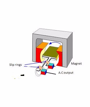 When the coil is vertical, no cutting of the magnetic lines of force takes place although the number of lines linking the coil is maximum. The rate of change magnetic flux is zero and as a result, no a.m. is induced in the coil.When the armature is parallel to the magnetic field, the rate of change of magnetic flux is maximum and the motion of the coil is perpendicular to the magnetic field, hence an a.m. is induced along the sides of the coil.After a 180° turn, starting from the vertical position, the sides of the loop interchange and the current in the loop is reversed. This means that the a.m. is positive for one half of the cycle and negative for the half. The maximum induced a.m. is at 90° rotation from the vertical position and the minimum is at 270° rotation. If there is an external circuit, the current through it would also have a maximum value at 90° and minimum at 270°.This kind of current is called an alternating current and the corresponding a.m. is the alternating e.m.f.The number of cycles produced per second is called the frequencyof the arc. The arc obtained is led to an external circuit through the slip rings and the carbon brushes.D.C generatorIt is made by replacing the slip rings in the arc generator with a commentator. Each half of the commentator ring is called a commentator segment and is insulated from the other half. Each end of the rotating loop of the wires connected to a commentator segment. Two carbon brushes connected to the outside circuit rest against the rotating commentator.In the deck generator, the commentator rotates with the loop of wire, just as the slip rings do with the rotor of an arc generator.
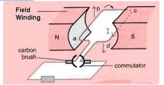 When the loop is rotated in the magnetic field, the induced e.m.f is still in alternating form. However after rotation of 180° instead of the current reversing, the connections to the external circuit are reversed so that the current direction in the external circuit remains the same.The output of a d.c generator is shown below.
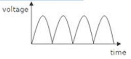 Note:The lower half of the cycle is not cut off but is reversed.Simple Step-up and Step-down TransformerConstruct a simple step-up and step-down transformerA transformer is the device that uses mutual induction between two coils to convert an a.c across one coil to a larger or smaller a.c across the other coil.A transformer is made up of two coils, each with a different number of loops linked by an iron core so that the magnetic flux from one passes through the other. When the flux generated by one coil changes the flux passing through the other will change, inducing a voltage in the second coil.The coil that provides the flux that is the coil connected to the a.c power source is known as the primary coil while the coil in which the voltage is induced is known as the secondary coil.When the number of turns in the primary coil (N) is lower than the number in the secondary coil (N),the secondary voltage will be lower than the secondary voltage. This is called the step-down transformer. The opposite of this is called the step-up transformer.Activity 1Construct a simple step-up and step-down transformer.
 - TOPIC 3: RADIOACTIVITY
The Nucleus of an AtomThe Structure of the Nucleus of an AtomDescribe the structure of the nucleus of an atomThe word atom is derived from the Greek word atom which means indivisible. The Greeks concluded that matter could be broken down into particles to small to be seen. These particles were called atoms.Atoms are composed of three type of particles: protons, neutrons, and electron.Protons and neutrons are responsible for most of the atomic mass e.g in a 150 person 149 lbs, 15 oz are protons and neutrons while only 1 oz. is electrons.The mass of an electron is very small (9.108 X 10⁻²⁸ grams).Both the protons and neutrons reside in the nucleus. Protons have a positive (+) charge, neutrons have no charge i.e they are neutral. Electrons reside in orbitals around the nucleus. They have a negative charge (-).It is the number of protons that determines the atomic number, e.g., H = 1. The number of protons in an element is constant (e.g., H=1, Ur=92) but neutron number may vary, so mass number (protons + neutrons) may vary.The same element may contain varying numbers of neutrons; these forms of an element are called isotopes. The chemical properties of isotopes are the same, although the physical properties of some isotopes may be different.Some isotopes are radioactive-meaning they "radiate" energy as they decay to a more stable form, perhaps another element half-life: time required for half of the atoms of an element to decay into stable form. Another example is oxygen, with atomic number of 8 can have 8, 9, or 10 neutrons.The Atomic Number, Mass Number and Isotopes of an Element and their SymbolsExplain the atomic number, mass number and isotopes of an element and their symbolsThe atomic number of a chemical element (also known as its proton number) is the number of protons found in the nucleus of an atom of that element.Therefore it is identical to the charge number of the nucleus. It is conventionally represented by the symbol Z.The atomic number uniquely identifies a chemical element. In an uncharged atom, the atomic number is also equal to the number of electrons.The atomic number, Z, should not be confused with the mass number, A.Mass number is the number of nucleons, i. e the total number of protons and neutrons in the nucleus of an atom. ---The number of neutrons, N, is known as the neutron number of the atom; thus, A = Z + N (these quantities are always whole numbers).Since protons and neutrons have approximately the same mass (and the mass of the electrons is negligible for many purposes) and the mass defect of nucleon binding is always small compared to the nucleon mass, the atomic mass of any atom, when expressed in unified atomic mass units (making a quantity called the "relative isotopic mass"), is roughly (to within 1%) equal to the whole number A.IsotopesIsotopes are atoms with the same atomic number Z but different neutron numbers N, and hence different atomic masses.A little more than three-quarters of naturally occurring elements exist as a mixture of isotopes (see monoisotopic elements), and the average isotopic mass of an isotopic mixture for an element (called the relative atomic mass) in a defined environment on Earth, determines the element's standard atomic weight.Historically, it was these atomic weights of elements (in comparison to hydrogen) that were the quantities measurable by chemists in the 19th century.The chemical properties of isotopes are the same, although the physical properties of some isotopes may be different.Some isotopes are radioactive-meaning they "radiate" energy as they decay to a more stable form, perhaps another element half-life: time required for half of the atoms of an element to decay into stable form. Another example is oxygen, with atomic number of 8 can have 8, 9, or 10 neutrons.Forces Holding the NucleusMention forces holding the nucleusStable and unstable atomsThere are forces within the atom that account for the behavior of the protons, neutrons, and electrons. Without these forces, an atom could not stay together.Recall that protons have a positive charge, electrons a negative charge, and neutrons are neutral. According to the laws of physics, like charges repel each other and unlike charges attract each other. A force called the strong force opposes and overcomes the force of repulsion between the protons and holds the nucleus together.The net energy associated with the balance of the strong force and the force of repulsion is called the binding energy. The electrons are kept in orbit around the nucleus because there is an electromagnetic field of attraction between the positive charge of the protons and the negative charge of the electrons.In some atoms, the binding energy is great enough to hold the nucleus together. The nucleus of this kind of atom is said to be stable. In some atoms the binding energy is not strong enough to hold the nucleus together, and the nuclei of these atoms are said to be unstable. Unstable atoms will lose neutrons and protons as they attempt to become stable.- Binding energy is the net energy that is the result of the balance with the strong force and the repulsive force, and this is the amount of energy that holds the nucleus together.
- A stable atom is an atom that has enough binding energy to hold the nucleus together permanently.
- An unstable atom does not have enough binding energy to hold the nucleus together permanently and is called a radioactive atom.
Natural RadioactivityThe Concept of RadioactivityExplain the concept of radioactivityRadioactive decay, also known as nuclear decay or radioactivity, is the process by which a nucleus of an unstable atom loses energy by emitting ionising radiation.A material that spontaneously emits such radiation — which includes alpha particles, beta particles, gamma rays and conversion electrons — is considered radioactive.Radioactive decay is a stochastic (i.e. random) process at the level of single atoms, in that, according to quantum theory, it is impossible to predict when a particular atom will decay.The chance that a given atom will decay never changes, that is, it does not matter how long the atom has existed. For a large collection of atoms however, the decay rate for that collection can be calculated from their measured decay constants or half-lives. The half-lives of radioactive atoms have no known limits for shortness or length of duration, and range over 55 orders of magnitude in time.Properties of the Radiations Emitted by Radio-active SubstancesDescribe properties of the radiations emitted by radio-active substancesThere are many types of radioactive decay . A decay, or loss of energy, results when an atom with one type of nucleus, called the parent radionuclide (or parent radioisotope), transforms into an atom with anucleus in a different state, or with a nucleus containing a different number of protons and neutrons. The product is called the daughter nuclide. In some decays, the parent and the daughter nuclides are different chemical elements, and thus the decay process results in the creation of an atom of a different element. This is known as a nuclear transmutation.The Nuclear Changes due to the Emission of Alpha ('8c'b1), Beta ('8cuc0u8804 ) and Gamma ('8cu8805 ) RadiationsExplain the nuclear changes due to the emission of Alpha ('8c'b1), Beta ('8cuc0u8804 ) and Gamma ('8cu8805 ) radiationsProperties of Alpha Rays- Alpha rays or alpha particles are the positively charged particles.
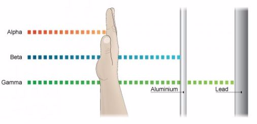
- Alpha particles have the least penetration power. They cannot penetrate the skin but this does not mean that they are not dangerous.
- Since they have a great ionisation power, so if they get into the body they can cause serious damage. They have the ability of ionising numerous atoms a short distance. It is due to this reason that the radioactive substance that releases alpha particles needs to be handled with rubber gloves. It should not be inhaled, eaten or allowed near open cuts.
Properties of Beta Rays.- Beta particles are highly energetic electrons which are released from inside of a nucleus.
- They are negatively charged and have a negligible mass.
- Beta particles have a greater penetration power than the alpha particles and can easily travel through the skin.
- Though beta particles have less ionisation power than the alpha particles but still they are dangerous and so their contact with the body must be avoided.
Properties of Gamma Rays- They have greatest power of penetration.
- They are the least ionizing but most penetrating and it is extremely difficult to stop them from entering the body.
- These rays carry huge amount of energy and can even travel through thin lead and thick concrete.
 The Detection of '8c'b1, '8cuc0u8804 and '8cu8805 RadiationsExplain the detection of '8c'b1, '8cuc0u8804 and '8cu8805 radiationsGeiger Counter, with Geiger-Mueller (GM) Tube or ProbeA GM tube is a gas-filled device that, when a high voltage is applied, creates an electrical pulse when radiation interacts with the wall or gas in the tube. These pulses are converted to a reading on the instrument meter.If the instrument has a speaker, the pulses also give an audible click. Common readout units are roentgens per hour (R/ hr), milliroentgens per hour (mR/hr), rem per hour (rem/hr), millirem per hour (mrem/hr), and counts per minute (cpm).GM probes (e.g., "pancake" type) are most often used with handheld radiation survey instruments for contamination measurements. However, energy-compensated GM tubes may be employed for exposure measurements.Further, often the meters used with a GM probe will also accommodate other radiation-detection probes. For example, a zinc sulfide (ZnS) scintillator probe, which is sensitive to just alpha radiation, is often used for field measurements where alpha-emitting radioactive materials need to be measured.
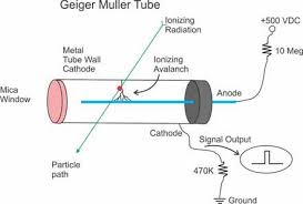 Spark counterThis consists of a fine metal gauze mounted about a millimetre away from a thin wire.A voltage is applied between the two so that sparking takes place between them - this usually requires some 4000 - 5000 V. The voltage is then reduced until sparking just stops.If an alpha-source is brought up close to the gauze it will ionise the air, and sparks will occur between the gauze and wire. With beta and gamma sources insufficient ions are usually produced for sparking to take place.The spark counter can be used to measure the range of alpha-particles.
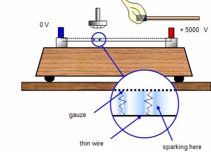 Cloud chamberThe cloud chamber, also known as the Wilson chamber, is a particle detector used for detecting ionising radiation.Rare picture shows in a single shot the 4 particles that we can detect in a cloud chamber: proton, electron, muon (probably) and alpha. In its most basic form, a cloud chamber is a sealed environment containing a supersaturated vapor of water or alcohol.When a charged particle (for example, an alpha or beta particle) interacts with the mixture, the fluid is ionized. The resulting ions act as condensation nuclei, around which a mist will form (because the mixture is on the point of condensation).The high energies of alpha and beta particles mean that a trail is left, due to many ions being produced along the path of the charged particle. These tracks have distinctive shapes (for example, an alpha particle's track is broad and shows more evidence of deflection by collisions, while an electron's is thinner and straight).When any uniform magnetic field is applied across the cloud chamber, positively and negatively charged particles will curve in opposite directions, according to the Lorentz force law with two particles of opposite charge.
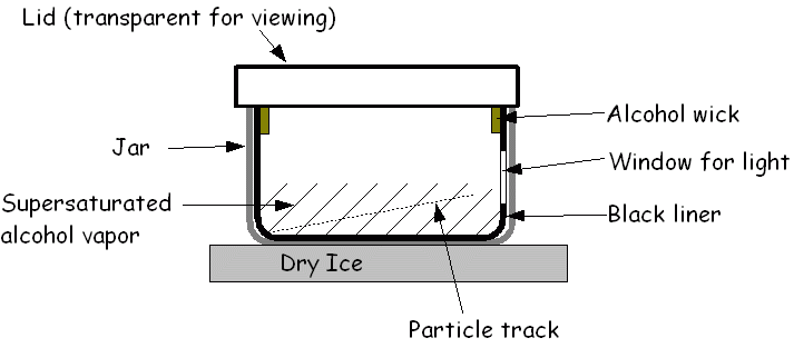 Other devices used to detect radiation include:
- Photographic film
- Bubble chamber
- Gold-leaf electroscope
Half-Life as Applied to a Radioactive SubstanceDescribe half-life as applied to a radioactive substanceHalf life can be defined as the time taken for the number of nuclei in a radioactive material to halve. It can also be defined as the time taken for the count rate of a sample of radioactive material to fall to half of its starting level.The count rate is measured by using an instrument called a Geiger-Muller tube over a period of time. A Geiger-Muller tube detects radiations by absorbing the radiation and converting it into an electrical pulse which triggers a counter and is displayed as a count rate.The release of radiation by unstable nuclei is called radioactive decay. This process occurs naturally and cannot be influenced by chemical or physical processes.The release of radiation is also a random event and overtime the activity of the radioactive material decreases. It is not possible to predict when an individual nucleus in a radioactive material will decay.But it is possible to measure the time taken for half of the nuclei in a radioactive material to decay. This is called the half life of radioactive material or radioisotope.The Half-Life of a Radioactive ElementDetermine the half-life of a radioactive elementAn exponential decay process can be described by any of the following three equivalent formulas: where
where- N0 is the initial quantity of the substance that will decay (this quantity may be measured in grams, moles, number of atoms, etc).
- N(t) is the quantity that still remains and has not yet decayed after a time t.
- t1⁄2 is the half-life of the decaying quantity.
- τis a positive number called the mean lifetime of the decaying quantity.
- λis a positive number called the decay constant of the decaying quantity.
 Where ln (2) is the natural logarithm of 2 (approximately 0.693).By plugging in and manipulating these relationships, we get all of the following equivalent descriptions of exponential decay, in terms of the half-life:
 The Application of a Natural Radioactive SubstancesIdentify the applications of a natural radioactive SubstancesMedical UsesHospitals, doctors, and dentists use a variety of nuclear materials and procedures to diagnose, monitor, and treat a wide assortment of metabolic processes and medical conditions in humans. In fact, diagnostic x-rays or radiation therapy have been administered to about 7 out of every 10 Americans. As a result, medical procedures using radiation have saved thousands of lives through the detection and treatment of conditions ranging from hyperthyroidism to bone cancer.The most common of these medical procedures involves the use of x-rays — a type of radiation that can pass through our skin. When x-rayed, our bones and other structures cast shadows because they are denser than our skin, and those shadows can be detected on photographic film. The effect is similar to placing a pencil behind a piece of paper and holding the pencil and paper in front of a light. The shadow of the pencil is revealed because most light has enough energy to pass through the paper, but the denser pencil stops all the light. The difference is that x-rays are invisible, so we need photographic film to "see" them for us. This allows doctors and dentists to spot broken bones and dental problems.X-rays and other forms of radiation also have a variety of therapeutic uses. When used in this way, they are most often intended to kill cancerous tissue, reduce the size of a tumor, or reduce pain. For example, radioactive iodine (specifically iodine-131) is frequently used to treat thyroid cancer, a disease that strikes about 11,000 Americans every year.X-ray machines have also been connected to computers in machines called computerized axial tomography (CAT) or computed tomography (CT) scanners. These instruments provide doctors with color images that show the shapes and details of internal organs. This helps physicians locate and identify tumors, size anomalies, or other physiological or functional organ problems.In addition, hospitals and radiology centers perform approximately 10 million nuclear medicine procedures in the United States each year. In such procedures, doctors administer slightly radioactive substances to patients, which are attracted to certain internal organs such as the pancreas, kidney, thyroid, liver, or brain, to diagnose clinical conditions.Academic and Scientific ApplicationsUniversities, colleges, high schools, and other academic and scientific institutions use nuclear materials in course work, laboratory demonstrations, experimental research, and a variety of health physics applications. For example, just as doctors can label substances inside people's bodies, scientists can label substances that pass through plants, animals, or our world. This allows researchers to study such things as the paths that different types of air and water pollution take through the environment. Similarly, radiation has helped us learn more about the types of soil that different plants need to grow, the sizes of newly discovered oil fields, and the tracks of ocean currents.In addition, researchers use low-energy radioactive sources in gas chromatography to identify the components of petroleum products, smog and cigarette smoke, and even complex proteins and enzymes used in medical research.Archaeologists also use radioactive substances to determine the ages of fossils and other objects through a process called carbon dating. For example, in the upper levels of our atmosphere, cosmic rays strike nitrogen atoms and form a naturally radioactive isotope called carbon-14. Carbon is found in all living things, and a small percentage of this is carbon-14. When a plant or animal dies, it no longer takes in new carbon and the carbon-14 that it accumulated throughout its life begins the process of radioactive decay. As a result, after a few years, an old object has a lower percent of radioactivity than a newer object. By measuring this difference, archaeologists are able to determine the object's approximate age.Industrial UsesWe could talk all day about the many and varied uses of radiation in industry and not complete the list, but a few examples illustrate the point. In irradiation, for instance, foods, medical equipment, and other substances are exposed to certain types of radiation (such as x-rays) to kill germs without harming the substance that is being disinfected — and without making it radioactive. When treated in this manner, foods take much longer to spoil, and medical equipment (such as bandages, hypodermic syringes, and surgical instruments) are sterilized without being exposed to toxic chemicals or extreme heat. As a result, where we now use chlorine — a chemical that is toxic and difficult-to-handle — we may someday use radiation to disinfect our drinking water and kill the germs in our sewage. In fact, ultraviolet light (a form of radiation) is already used to disinfect drinking water in some homes.Similarly, radiation is used to help remove toxic pollutants, such as exhaust gases from coal-fired power stations and industry. For example, electron beam radiation can remove dangerous sulphur dioxides and nitrogen oxides from our environment. Closer to home, many of the fabrics used to make our clothing have been irradiated (treated with radiation) before being exposed to a soil-releasing or wrinkle-resistant chemical. This treatment makes the chemicals bind to the fabric, to keep our clothing fresh and wrinkle-free all day, yet our clothing does not become radioactive. Similarly, nonstick cookware is treated with gamma rays to keep food from sticking to the metal surface.The agricultural industry makes use of radiation to improve food production and packaging. Plant seeds, for example, have been exposed to radiation to bring about new and better types of plants. Besides making plants stronger, radiation can be used to control insect populations, thereby decreasing the use of dangerous pesticides. Radioactive material is also used in gauges that measure the thickness of eggshells to screen out thin, breakable eggs before they are packaged in egg cartons. In addition, many of our foods are packaged in polyethylene shrink-wrap that has been irradiated so that it can be heated above its usual melting point and wrapped around the foods to provide an airtight protective covering.All around us, we see reflective signs that have been treated with radioactive tritium and phosphorescent paint. Ionizing smoke detectors, using a tiny bit of americium-241, keep watch while we sleep. Gauges containing radioisotopes measure the amount of air whipped into our ice cream, while others prevent spillover as our soda bottles are carefully filled at the factory.Engineers also use gauges containing radioactive substances to measure the thickness of paper products, fluid levels in oil and chemical tanks, and the moisture and density of soils and material at construction sites. They also use an x-ray process, called radiography, to find otherwise imperceptible defects in metallic castings and welds. Radiography is also used to check the flow of oil in sealed engines and the rate and way that various materials wear out. Well-logging devices use a radioactive source and detection equipment to identify and record formations deep within a bore hole (or well) for oil, gas, mineral, groundwater, or geological exploration. Radioactive materials also power our dreams of outer space, as they fuel our spacecraft and supply electricity to satellites that are sent on missions to the outermost regions of our solar system.Nuclear Power PlantsElectricity produced by nuclear fission — splitting the atom — is one of the greatest uses of radiation. As our country becomes a nation of electricity users, we need a reliable, abundant, clean, and affordable source of electricity. We depend on it to give us light, to help us groom and feed ourselves, to keep our homes and businesses running, and to power the many machines we use. As a result, we use about one-third of our energy resources to produce electricity.Electricity can be produced in many ways — using generators powered by the sun, wind, water, coal, oil, gas, or nuclear fission. In America, nuclear power plants are the second largest source of electricity (after coal-fired plants) — producing approximately 21 percent of our Nation's electricity.The purpose of a nuclear power plant is to boil water to produce steam to power a generator to produce electricity. While nuclear power plants have many similarities to other types of plants that generate electricity, there are some significant differences. With the exception of solar, wind, and hydroelectric plants, power plants (including those that use nuclear fission) boil water to produce steam that spins the propeller-like blades of a turbine that turns the shaft of a generator. Inside the generator, coils of wire and magnetic fields interact to create electricity. In these plants, the energy needed to boil water into steam is produced either by burning coal, oil, or gas (fossil fuels) in a furnace, or by splitting atoms of uranium in a nuclear power plant. Nothing is burned or exploded in a nuclear power plant. Rather, the uranium fuel generates heat through a process called fission.Nuclear power plants are fueled by uranium, which emits radioactive substances. Most of these substances are trapped in uranium fuel pellets or in sealed metal fuel rods. However, small amounts of these radioactive substances (mostly gases) become mixed with the water that is used to cool the reactor. Other impurities in the water are also made radioactive as they pass through the reactor. The water that passes through a reactor is processed and filtered to remove these radioactive impurities before being returned to the environment. Nonetheless, minute quantities of radioactive gases and liquids are ultimately released to the environment under controlled and monitored conditionsThe U.S. Nuclear Regulatory Commission (NRC) has established limits for the release of radioactivity from nuclear power plants. Although the effects of very low levels of radiation are difficult to detect, the NRC's limits are based on the assumption that the public's exposure to man-made sources of radiation should be only a small fraction of the exposure that people receive from natural background sources.Experience has shown that, during normal operations, nuclear power plants typically release only a small fraction of the radiation allowed by the NRC's established limits. In fact, a person who spends a full year at the boundary of a nuclear power plant site would receive an additional radiation exposure of less than 1 percent of the radiation that everyone receives from natural background sources. This additional exposure, totaling about 1 millirem (a unit used in measuring radiation absorption and its effects), has not been shown to cause any harm to human beings.In agricultureRadioisotopes are used to induce mutations in plants in order to develop superior varieties that are harder and more resistant to diseases.
- Artificial RadioactivityDifference between Natural and Artificial RadioactivityDistinguish between natural and artificial radioactivityArtificial radioactivity is the phenomenon by which even light elements are made radioactive by artificial or induced methods.Artificial radioactivity occurs when a previously stable material has been made radioactive by exposure to specific radiation. Most radioactivity does not induce other material to become radioactive. This Induced radioactivity was discovered by Irène Curie and F. Joliot in 1934. This is also known as man-made radioactivity. The phenomenon by which even light elements are made radioactive by artificial or induced methods is called artificial radioactivity.Curie and Joliot showed that when lighter elements such as boron and aluminium were bombarded with α-particles, there was a continuous emission of radioactive radiations, even after the α−source had been removed. They showed that the radiation was due to the emission of a particle carrying one unit positive charge with mass equal to that of an electron.Neutron activation is the main form of induced radioactivity, which happens when free neutrons are captured by nuclei. This new heavier isotope can be stable or unstable (radioactive) depending on the chemical element involved.Because free neutrons disintegrate within minutes outside of an atomic nucleus, neutron radiation can be obtained only from nuclear disintegrations, nuclear reactions, and high-energy reactions (such as in cosmic radiation showers or particle accelerator collisions). Neutrons that have been slowed down through a neutron moderator (thermal neutrons) are more likely to be captured by nuclei than fast neutrons.Methods of Producing Artificial Radioactive IsotopesDescribe methods of producing artificial radioactive isotopesMethods of inducing radioactivity
- Nuclear activation:Neutron activationis the process in which neutron radiation induces radioactivity in materials, and occurs when atomic nuclei capture free neutrons, becoming heavier and entering excited states. The excited nucleus often decays immediately by emitting gamma rays, or particles such as beta particles, alpha particles, fission products and neutrons (in nuclear fission). Thus, the process of neutron capture, even after any intermediate decay, often results in the formation of an unstable activation product. Such radioactive nuclei can exhibit half-lives ranging from small fractions of a second to many years.
- Photonuclear reactions: A photonuclear reaction is a reaction resulting from an interaction between a photon and a nucleus.-During a photonuclear reaction energy of a gamma-ray photon is fully or partially absorbed by the nucleus forcing it into and excited state. From this excited state the nucleus can emit any particle, provided it has enough energy for such a process to occur. Most commonly it will emit a photon, but also a neutron (n), a proton (p) or an alpha (α) particle can be emitted.
Applications of Artificial RadioactivityMention the applications of artificial radioactivityApplication of artificial radioactivity include:- Radiation safety:For physicians and radiation safety officers, activation of sodium in the human body to sodium-24, and phosphorus to phosphorus-32, can give a good immediate estimate of acute accidental neutron exposure.
- Neutron detection:One way to demonstrate that nuclear fusion has occurred inside a fusor device is to use a Geiger counter to measure the gamma ray radioactivity that is produced from a sheet of aluminum foil.In the ICF fusion approach, the fusion yield of the experiment (directly proportional to neutron production) is usually determined by measuring the gamma-ray emissions of aluminum or copper neutron activation targets.Aluminum can capture a neutron and generate radioactive sodium-24, which has a half-life of 15 hours[7][8] and a beta decay energy of 5.514 MeV.The activation of a number of test target elements such as sulfur, copper, tantalum and gold have been used to determine the yield of both pure fissionand thermonuclearweapons.
- Materials analysis:Main article: neutron activation analysis. Neutron activation analysis is one of the most sensitive and accurate methods of trace element analysis. It requires no sample preparation or solubilization and can therefore be applied to objects that need to be kept intact such as a valuable piece of art. Although the activation induces radioactivity in the object, its level is typically low and its lifetime may be short, so that its effects soon disappear. In this sense, neutron activation is a non-destructive analysis method.
- The potential use of photonuclear reactions for a range of applications is described. These are: photonuclear transmutation doping of semiconductors, neutron production from electron linacs, quality checking of radioactive waste, fission product incineration, photoexcitation of isomers for dosimetry, and nuclear resonance fluorescence for materials analysis. Initial brief descriptions of atomic and nuclear interactions of photons and of bremsstrahlung are given.
Radiation Hazards and SafetyThe Effects of Nuclear Radiation on Human BodyExplain the effects of nuclear radiation on human bodyCertain body parts are more specifically affected by exposure to different types of radiation sources. Several factors are involved in determining the potential health effects of exposure to radiation. These include:- The size of the dose (amount of energy deposited in the body)
- The ability of the radiation to harm human tissue
- Which organs are affected
The most important factor is the amount of the dose - the amount of energy actually deposited in your body. The more energy absorbed by cells, the greater the biological damage. Health physicists refer to the amount of energy absorbed by the body as the radiation dose. The absorbed dose, the amount of energy absorbed per gram of body tissue, is usually measured in units called rads. Another unit of radation is the rem, or roentgen equivalent in man. To convert rads to rems, the number of rads is multiplied by a number that reflects the potential for damage caused by a type of radiation. For beta, gamma and X-ray radiation, this number is generally one. For some neutrons, protons, or alpha particles, the number is twenty.- Hair:The losing of hair quickly and in clumps occurs with radiation exposure at 200 rems or higher.
- Brain:Since brain cells do not reproduce, they won't be damaged directly unless the exposure is 5,000 rems or greater. Like the heart, radiation kills nerve cells and small blood vessels, and can cause seizures and immediate death.
- Thyroid:The certain body parts are more specifically affected by exposure to different types of radiation sources. The thyroid gland is susceptible to radioactive iodine. In sufficient amounts, radioactive iodine can destroy all or part of the thyroid. By taking potassium iodide can reduce the effects of exposure.
- Blood System:When a person is exposed to around 100 rems, the blood's lymphocyte cell count will be reduced, leaving the victim more susceptible to infection. This is often refered to as mild radiation sickness. Early symptoms of radiation sickness mimic those of flu and may go unnoticed unless a blood count is done. According to data from Hiroshima and Nagaski, show that symptoms may persist for up to 10 years and may also have an increased long-term risk for leukemia and lymphoma. For more information, visit Radiation Effects Research Foundation.
- Heart:Intense exposure to radioactive material at 1,000 to 5,000 rems would do immediate damage to small blood vessels and probably cause heart failure and death directly.
- Gastrointestinal Tract:Radiation damage to the intestinal tract lining will cause nausea, bloody vomiting and diarrhea. This is occurs when the victim's exposure is 200 rems or more. The radiation will begin to destroy the cells in the body that divide rapidly. These including blood, GI tract, reproductive and hair cells, and harms their DNA and RNA of surviving cells.
- Reproductive Tract:Because reproductive tract cells divide rapidly, these areas of the body can be damaged at rem levels as low as 200. Long-term, some radiation sickness victims will become sterile.
Radiation sicknessRadiation sickness results when humans (or other animals) are exposed to very large doses of ionizing radiation. Radiation exposure can occur as a single large exposure (acute), or a series of small exposures spread over time (chronic). Exposure may be accidental or intentional (as in radiation therapy).Causes- Accidental exposure to high doses of radiation such as a nuclear power plant accidents.
- Exposure to excessive radiation for medical treatments.
Symptoms- Bleeding from the nose, mouth, gums, and rectum
- Bloody stool
- Bruising
- Confusion
- Dehydration
- Diarrhea
- Fainting
- Fatigue
- Fever
- Hair loss
- Inflammation of exposed areas (redness, tenderness, swelling, bleeding)
- Mouth ulcers
- Nausea and vomiting
- Open sores on the skin
- Skin burns (redness, blistering)
- Sloughing of skin
- Ulcers in the esophagus, stomach or intestines
- Vomiting blood
- Weakness
First Aid- Check the person's breathing and pulse.
- Start CPR, if necessary.
- Remove the person's clothing and place the items in a sealed container. This stops ongoing contamination.
- Vigorously wash body with soap and water.
- Dry the body and wrap with soft, clean blanket.
- Call for emergency medical help or take the person to nearest emergency medical facility if you can do so safely.
How to Protect yourself from Nuclear Radiation HazardsProtect himself/herself from nuclear radiation hazardsPrecautions- Time:An average the procedure time for a diagnostic coronary angiogram is approximately 30 minutes and an interventional procedure PCI or EPS/pacing would take between 90 to 120 minutes. However the fluoroscopic and the cine screening time are highly variable depending on the nature of the procedure and the experience of the operator. The lower the amount of time spent in a radiation area, the lower the exposure will be. Significant reductions can be achieved when an activity is delayed until after cine imaging is completed. Every effort should be made by the operating cardiologist in the cath lab to minimise fluoroscopy and cine screening time.
- Distance:Increasing the distance from the radiation beam decreases the risk of exposure. doubling the distance between the primary beam and operator, reduces the exposure by a factor of four. In addition, the radiation exposure varies according to the angle at which the camera is projected Oblique views (left and right anterior oblique) and steep angulations increase radiation exposure but are often employed to improve visualisation. 60-degree angulations give up to three times the operator dose than 30-degree angulations (11). The second operator or assistant is generally less exposed to radiation compared to the first operator but certainly more at risk than the other staff in the room.
- Shielding:Lead shields and shielding will significantly reduce the risk of exposure but only if appropriately used and in proper working order. Protective equipment includes lead aprons, thyroid collars and leaded glasses. With the newly designed frames and ultra light lenses, protective leaded eyewear is now used by more of the cardiologists and staff in cardiac cath lab. Some cath labs also use overhanging lead screens to prevent radiation exposure to brain. The staff should wear a protective apron of at least 0.25 mm lead equivalent. Protective gloves should be of at least 0.35 mm lead equivalent. All such protective clothing should bear an identifying mark and should be examined at yearly intervals. Defective items should be withdrawn from use.
- Adhering to guideline and protocols:Every unit or work place that deals with ionising radiation should have their own local guidelines and rules for radiation safety. These must be read, understood and strictly adhered to in daily practice. Staff must comply with these local rules in order to insure that the Trust and all their employees do not contravene statutory requirements of the ionising radiation regulations and other relevant legislation.
- Minimising risk of exposure to staff and patients: The occupational limit of radiation exposure in the UK currently is estimated at 20 mSv per year averaged over five consecutive years (5). Every operator who undertakes a cardiovascular procedure in the cath lab is responsible for the amount of radiation exposure to the patient, his or her co-staff and to themselves. In the event of an incident where the patient might have been exposed to inadvertent excess radiation either due to clinical circumstances, malfunctioning of the equipment or operation errors, the radiation protection adviser should be informed of the incident. It is their duty to estimate the radiation dose received by the patient and also advise whether the incident is to be reported.Only essential staff shall be in the cath lab during radiation exposure. All persons not required in the room should leave the room during serial radiographic exposure. The operator shall stand behind a barrier if possible. People who must move around the room during the procedure should wear a wraparound protective garment. When possible, the cardiologist and all other personnel required in the room should step back from the table and behind portable shields during cine and serial radiography procedures. This action can decrease the exposure of the cardiologist and the other nearby personnel by a factor of three or more (10).
- TOPIC 4: THERMIONIC EMISSIONNuclear Fission and FusionThe Nuclear Fission and FusionExplain the nuclear fission and fusionNuclear fissionNuclear fission is either a nuclear reaction or a radioactive decay process in which the nucleus of an atom splits into smaller parts (lighter nuclei).The fission process often produces free neutrons and photons (in the form of gamma rays), and releases a very large amount of energy even by the energetic standards of radioactive decay. It is an exothermic reaction which can release large amounts of energy both as electromagnetic radiation and as kinetic energy of the fragments (heating the bulk material where fission takes place).In order for fission to produce energy, the total binding energy of the resulting elements must be less negative (higher energy) than that of the starting element.Nuclear fusionNuclear fusion is a nuclear reaction in which two or more atomic nuclei come very close and then collide at a very high speed and join to form a new type of atomic nucleus.During this process, matter is not conserved because some of the matter of the fusing nuclei is converted to photons (energy).The fusion of two nuclei with lower masses than iron (which, along with nickel, has the largest binding energy per nucleon) generally releases energy, while the fusion of nuclei heavier than iron absorbs energy.The opposite is true for the reverse process, nuclear fission. This means that fusion generally occurs for lighter elements only, and likewise, that fission normally occurs only for heavier elements.Application of Nuclear Fission and FusionMention the applications of nuclear fission and fusionNuclear fission is used in:
- Nuclear power plants to generate electricity for domestic and industrial use.
- In making nuclear bombs.
Nuclear fusion is used in:- In fussion power plants to make electricity.
- To make nuclear weapons such as the hydrogen bombs.
- Thermionic EmissionThermionic emission is the discharge of electrons from heated materials, widely used as a source of electrons in conventional electron tubes (e.g., television picture tubes) in the fields of electronics and communications. The phenomenon was first observed (1883) by Thomas A. Edison as a passage of electricity from a filament to a plate of metal inside an incandescent lamp. The classical example of thermionic emission is the emission of electrons from a hot cathode into a vacuum (also known as thermal electron emission or the Edison effect) in a vacuum tube. The hot cathode can be a metal filament, a coated metal filament, or a separate structure of metal or carbides or borides of transition metals. Vacuum emission from metals tends to become significant only for temperatures over 1000 K. The science dealing with this phenomenon has been known as "thermionics," but this name seems to be gradually falling into disuse.
Cathode RaysCathode rays (also called an electron beam or e-beam) are streams of electrons observed in vacuum tubes.Electrons were first discovered as the constituents of cathode rays. In 1897 British physicist J. J. Thomson showed the rays were composed of a previously unknown negatively charged particle, which was later named the electron. Cathode ray tubes (CRTs) use a focused beam of electrons deflected by electric or magnetic fields to create the image in a classic television set.The Production of Cathode RaysExplain the production of cathode raysCathode rays are so named because they are emitted by the negative electrode, or cathode, in a vacuum tube. To release electrons into the tube, they first must be detached from the atoms of the cathode.Modern vacuum tubes use thermionic emission, in which the cathode is made of a thin wire filament which is heated by a separate electric current passing through it. The increased random heat motion of the filament atoms knocks electrons out of the atoms at the surface of the filament, into the evacuated space of the tube.Since the electrons have a negative charge, they are repelled by the cathode and attracted to the anode. They travel in straight lines through the empty tube. The voltage applied between the electrodes accelerates these low mass particles to high velocities. Cathode rays are invisible, but their presence was first detected in early vacuum tubes when they struck the glass wall of the tube, exciting the atoms of the glass and causing them to emit light, a glow called fluorescence.Researchers noticed that objects placed in the tube in front of the cathode could cast a shadow on the glowing wall, and realized that something must be travelling in straight lines from the cathode.After the electrons reach the anode, they travel through the anode wire to the power supply and back to the cathode, so cathode rays carry electric current through the tube. The current in a beam of cathode rays through a tube can be controlled by passing it through a metal screen of wires (a grid) to which a small voltage is applied.The electric field of the wires deflects some of the electrons, preventing them from reaching the anode. Thus a small voltage on the grid can be made to control a much larger voltage on the anode. This is the principle used in vacuum tubes to amplify electrical signals.High speed beams of cathode rays can also be steered and manipulated by electric fields created by additional metal plates in the tube to which voltage is applied, or magnetic fields created by coils of wire (electromagnets). These are used in cathode ray tubes, found in televisions and computer monitors, and in electron microscopes. The Properties of Cathode RaysState the properties of cathode raysProperties of Cathode Rays Include:
- Cathode rays travel in straight lines. That is why, cathode rays cast shadow of any solid object placed in their path. The path cathode rays travel is not affected by the position of the anode.
- Cathode rays consist of matter particles, and posses energy by the virtue of its mass and velocity. Cathode rays set a paddle wheel into motion when it is placed in the path of these rays one the bladder of the paddle wheel.
- Cathode rays consist of negatively charged particles. When cathode rays are subjected to an electrical field, these get deflected towards the positively charge plate (Anode).We know that a positively charged body would attract only a negatively charged body, therefore the particles of cathode rays carry negative charge.Cathode rays also get deflected when these are subjected to a strong magnetic field.
- Cathode rays heat the object only which they fall. The cathode ray particles possess kinetic energy. When these particles strike an object, a part of the kinetic energy is transferred to the object. The causes a rise in the temperature of the object.
- Cathode rays cause green fluorescence on glass surface, i.e., the glass surface only which the cathode rays strike show a colored shine.
- Cathode rays can penetrate through thin metallic sheets.
- Cathode rays ionize the gases through which they travel.
- Cathode rays when fall only certain metals such as copper, but rays produced. The X-rays are not deflected by electrical or magnetic fields. X-rays pass through opaque materials such as black paper, but stopped by solid objects such as bones.
- Cathode rays travel with speed nearly equal to that of light.
The Application of Cathode Ray TubeState the application of cathode ray tubeApplication of cathode ray tube includes:TelevisionsBefore LCD or Plasma television, the CRT was used to create a moving image.It used the same principle as a CRT, and for Black and White televisions, that worked fine. B&W TVs were essentially the same thing as a CRT, as all that's needed is the control of the brightness of the beam.A CRT TV works by having the electron beam "scan" the screen at an rate faster than our eyes can perceive.This means that it shoots across the screen like a machine gun, and the images we see are actually made from many fluorescent dots.The fluorescence caused by the beam striking the screen lasts a bit longer so that the next scan can be made without the previous image disappearing.It scans twice each time, first filling in the odd "holes" then the even ones.Each scan is about 1/50 of a second.Colour CRT TVs had 3 electron guns rather than a single one, a shadow mask, and a modified fluorescent screen.The 3 electron guns were needed as there were three primary colours (Red, Green and Blue) that could be adjusted in different amounts to create any colour.The colours are formed as a result of the shadow mask, which is a layer with holes in it that controls the angle of the incoming electron beams. This is because the fluorescent screen is separated into multi-coloured phosphors that are placed adjacent to each other at small intervals.Thus it isn't actually a single coloured pixel, but rather 3 very small pixels that join together to form a larger dot.Cathode Ray OscilloscopesA Cathode Ray Oscilloscope (CRO) is a diagnostic device that allows one to "see" voltage.It is essential a Cathode Ray Tube with two perpendicular sets of deflecting electric plates.The vertical set is where an input voltage is plugged in for the oscilloscope to display.However, the horizontal set is connected to a "sweep generator".This is what provides a constant, but adjustable, timebase for the sweeping.It essentially creates a "sawtooth voltage."This is what causes the image to be animated, and measured with a linear scale.
X-Rays
The Structure and Mode of Action of the X-ray TubeDescribe the structure and mode of action of the x-ray tubeX-radiation (composed of X-rays) is a form of electromagnetic radiation. Electromagnetic radiation (EM radiation or EMR) is a form of radiant energy released by certain electromagnetic processes. Visible light is one type of electromagnetic radiation, other familiar forms are invisible electromagnetic radiations such as X-rays and radio waves.Most X-rays have a wavelength ranging from 0.01 to 10 nanometers, corresponding to frequencies in the range 30 pentahertz to 30 exahertz (3×10¹⁶ Hz to 3×10¹⁹ Hz) and energies in the range 100 eV to 100 keV.X-ray wavelengths are shorter than those of UV rays and typically longer than those of gamma rays.In many languages, X-radiation is referred to with terms meaning Röntgen radiation, after Wilhelm Röntgen, who is usually credited as its discoverer, and who had named it X-radiation to signify an unknown type of radiation.X-ray tubeThe x-ray tube consists of an emitter (either a filament or a cathode),which emits electrons into a vacuum and an anode to accelerate the electrons. This establishes a flow of electrons through the tube.These electrons are reffered to as a beam. The cathode is in the form of a filament which emits electrons when heated. The anode is made of copper and also carries the target.A high p.d between the anode and the cathode is maintained by an external high-voltage source. A battery that supplies high current is used to heat the cathode filament, which in many cases is made of tungsten. The cathode is in the form of a coil to provide high resistance to the passing current.Production of X-raysThe electrons from the filament experiences the p. d and accelerated towards the anode. When they hit the anode, they are stopped and thereby transfer their energy to the electrons of the anode material. This gives rise to x-rays.It is only a very small percentage of their energy that is converted to x-rays, with the rest of it being transformed to heat.
Defference between Soft and hard X-rays and their ProductionDistinguish between soft and hard x-rays and their productionX-rays may be classified as hard or soft depending on their wavelengths, which give rise to different properties.Differences between hard and soft x-raysHard x-rays Soft x-rays They have shorter wavelength(high frequency) They have longer wavelength They have higher energy Have less energy Thigher penetrating power Lower penetrating power Are produced by higher accelerating potential Produced by lower accelerating potential Have higher velocity Have lower velocity The Properties of X-raysState the properties of x-raysProperties of x-rays include:- They travel in straight lines.
- They readily penetrate matter.
- They are not affected by electric or magnetic fields(they have no charge).
- They cause fluorescence in certain substances.
- They can be detected by photographic emulsion.
- They ionise gases causing the gases to conduct electricity.
The Application of X-Rays in Daily LifeIdentify the applications of x-rays in daily lifeThe following are some uses of x-rays:- In the medical field
- Crystallography
- Astronomy
- X-ray microscopic analysis
- X-ray fluorescence
- Security installations
- Industries
-
TOPIC 5: ELECTRONICSemi ConductorsThe Concept of Energy Band in SolidsExplain the concept of energy bands in solidsIn solid-state physics, the electronic band structure (or simply band structure) of a solid describes those ranges of energy that an electron within the solid may have (called energy bands, allowed bands, or simply bands) and ranges of energy that it may not have (called band gaps or forbidden bands).Band theory derives these bands and band gaps by examining the allowed quantum mechanical wave functions for an electron in a large, periodic lattice of atoms or molecules. Band theory has been successfully used to explain many physical properties of solids, such as electrical resistivity and optical absorption, and forms the foundation of the understanding of all solid-state devices (transistors, solar cells, etc.).Difference between Conductors, Semiconductors and InsulatorsDistinguish between conductors, semiconductors and insulatorsInsulatorsAn electrical insulator is a material whose internal electric charges do not flow freely, and therefore make it impossible to conduct an electric current under the influence of an electric field. This contrasts with other materials, semiconductors and conductors, which conduct electric current more easily.The property that distinguishes an insulator is its resistivity; insulators have higher resistivity than semiconductors or conductors.A perfect insulator does not exist, because even insulators contain small numbers of mobile charges (charge carriers) which can carry current. In addition, all insulators become electrically conductive when a sufficiently large voltage is applied that the electric field tears electrons away from the atoms. This is known as the breakdown voltage of an insulator.Some materials such as glass, paper and Teflon, which have high resistivity, are very good electrical insulators. A much larger class of materials, even though they may have lower bulk resistivity, are still good enough to prevent significant current from flowing at normally used voltages, and thus are employed as insulation for electrical wiring and cables. Examples include rubber-like polymers and most plastics.ConductorsA conductor is an object or type of material that allows the flow of electrical current in one or more directions. For example, a wire is an electrical conductor that can carry electricity along its length.In metals such as copper or aluminum, the movable charged particles are electrons. Positive charges may also be mobile, such as the cationic electrolyte(s) of a battery, or the mobile protons of the proton conductor of a fuel cell. Insulators are non-conducting materials with few mobile charges and support only insignificant electric currents.SemiconductorsA semiconductor material has an electrical conductivity value falling between that of a conductor, such as copper, and an insulator, such as glass. Semiconductors are the foundation of modern electronics. Semiconducting materials exist in two types: elemental materials andcompound materials.The modern understanding of the properties of a semiconductor relies on quantum physics to explain the movement of electrons and holes in a crystal lattice. The unique arrangement of the crystal lattice makes silicon and germanium the most commonly used elements in the preparation of semiconducting materials.An increased knowledge of semiconductor materials and fabrication processes has made possible continuing increases in the complexity and speed of microprocessors and memory devices. Some of the information on this page may be outdated within a year because new discoveries are made in the field frequently.Examples of semiconductors are Silicon, Germanium.The Effects of Temperature on the Conductivity of Conductors, Semiconductors and InsulatorsDescribe the effect of temperature on the conductivity of conductors, semiconductors and insulatorsThe conductivity of pure defect free metal decreases with increase in temperature .With increased temperature in a metal, thermal energy causes atoms in metal to vibrate, in this excited state atoms interact with and scatter electrons.Thus decreasing the mean free path, and hence the mobility of electrons too decreases, and resistivity increases.Since, resistivity = 1/conductivityThe electrical conductivity of a semiconductor will increase exponentially with an increase in temperature, as temperature increases the electrons in the valance band will gain energy and go into the higher energy levels in the conduction band where they become charge carriers.The increase in conduction can also be explained, I guess,due to the formation of Cooper pairs and hence the creation of Phonon field.Types of SemiconductorsIdentify types of SemiconductorsThere are two types of semiconductors- Intrinsic semiconductors
- Extrinsic semiconductors
Intrinsic semiconductorsAn intrinsic semiconductor material is chemically very pure and possesses poor conductivity. It has equal numbers of negative carriers (electrons) and positive carriers (holes). Examples are Silicon and Germanium.A silicon crystal is different from an insulator because at any temperature above absolute zero temperature, there is a finite probability that an electron in the lattice will be knocked loose from its position, leaving behind an electron deficiency called a "hole."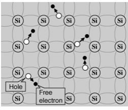 If a voltage is applied, then both the electron and the hole can contribute to a small current flow.The conductivity of a semiconductor can be modeled in terms of the band theory of solids.The band model of a semiconductor suggests that at ordinary temperatures there is a finite possibility thatelectrons can reach the conduction band and contribute to electrical conduction. The term intrinsic heredistinguishes between the properties of pure "intrinsic" silicon and the dramatically different properties ofdoped n-type or p-type semiconductors.The current flow in an intrinsic semiconductor is influenced by the density of energy states which in turn influencesthe electron density in the conduction band. This current is highly temperature dependent. The electrical conductivityof intrinsic semiconductors increase with increasing temperature.Extrinsic semiconductorsExtrinsic semiconductor is an improved intrinsic semiconductor with a small amount of impurities added by a process,known as doping, which alters the electrical properties of the semiconductor and improves its conductivity.Introducing impurities into the semiconductor materials (doping process) can control their conductivity.Doping process produces two groups of semiconductors:
- The negative charge conductor (n-type).
- The positive charge conductor (p-type).
Semiconductors are available as either elements or compounds. Silicon and Germanium are the most commonelemental semiconductors. Compound Semiconductors include InSb, InAs, GaP, GaSb, GaAs, SiC, GaN. Si and Geboth have a crystalline structure called the diamond lattice. That is, each atom has its four nearestneighbors at the corners of a regular tetrahedron with the atom itself being at the center.In addition to the pure element semiconductors, many alloys and compounds are semiconductors.The advantage of compound semiconductor is that they provide the device engineer with a wide range of energy gapsand mobilities, so that materials are available with properties that meet specific requirements. Some of thesesemiconductors are therefore called wide band gap semiconductors.The Mechanism of Doping Intrinsic SemiconductorsDescribe the mechanism of doping intrinsic semiconductorsThe addition of a small percentage of foreign atoms in the regular crystal lattice of silicon or germanium produces dramatic changes in their electrical properties, producing n-typeand p-type semiconductors.Pentavalent impuritiesThe addition of pentavalent impurities such as antimony,arsenic or phosphorous contributes free electrons, greatly increasing the conductivity of the intrinsic semiconductor. Phosphorous may be added by diffusion of phosphine gas (PH3).(5 valence electrons) produce n-type semiconductors by contributing extra electrons.
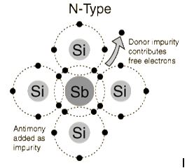 Trivalent impurities(3 valence electrons) produce p-type semiconductors by producing a "hole" or electron deficiency.N-Type SemiconductorThe addition of pentavalent impurities such as antimony, arsenic or phosphorous contributes free electrons,greatly increasing the conductivity of the intrinsic semiconductor. Phosphorous may be added by diffusion ofphosphine gas (PH3).
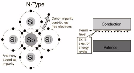 P-Type SemiconductorThe addition of trivalent impurities such as boron, aluminum or gallium to an intrinsic semiconductor creates deficiencies of valence electrons,called "holes". It is typical to use B2H6 diborane gas to diffuse boron into the silicon material.
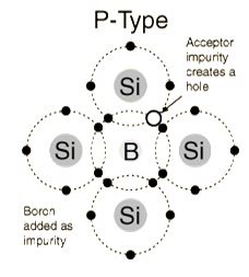 P-n junctionsP-n junctions are formed by joining n-type and p-type semiconductor materials.
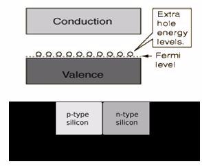 Since the n-type region has a high electron concentration and the p type a high hole concentration, electrons diffuse from the n-type side to the p-type side. Similarly, holes flow by diffusion from the p-type side to the n-type side.If the electrons and holes were not charged, this diffusion process would continue until the concentration of electrons and holes on the two sides were the same, as happens if two gasses come into contact with each other. However, in a p-n junction, when the electrons and holes move to the other side of the junction, they leave behind exposed charges on dopant atom sites, which are fixed in the crystal lattice and are unable to move.On the n-type side, positive ion cores are exposed. On the p-type side, negative ion cores are exposed. An electric field Ê forms between the positive ion cores in the n-type material and negative ion cores in the p-type material. This region is called the "depletion region" since the electric field quickly sweeps free carriers out, hence the region is depleted of free carriers.
DiodesA semiconductor diode is a crystalline piece of semiconductor material with a p–n junction connected to two electrical terminals.In electronics, a diode is a two-terminal electronic component with asymmetric conductance; it has low (ideally zero) resistance to current in one direction, and high (ideally infinite) resistance in the otherThe Construction of P-N JunctionDescribe the construction of P-N junctionWhen the polarity of the battery is such that electrons are allowed to flow through the diode, the diode is said to be forward-biased. Conversely, when the battery is “backward” and the diode blocks current, the diode is said to be reverse-biased. A diode may be thought of as like a switch: “closed” when forward-biased and “open” when reverse-biased.Diode behavior is analogous to the behavior of a hydraulic device called a check valve. A check valve allows fluid flow through it in only one direction.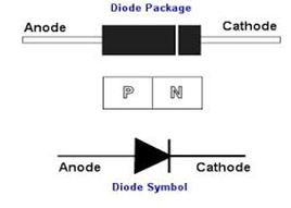 The Mode of Action a P-N JunctionExplain the mode of action of a P-N junctionIn a p-n junction, electrons cross over the boundary from the n-type material to holes in the p-type material. At the same time, holes cross over from the p-side to the n-side and capture electrons. This movement of holes and electrons causes the n-side to become positively charged and the p-side to become negatively charged. A p.d is created across the junction to stop further electron flow.The Types of DiodesIdentify the types of diodesThere are different types of diodes, the following are the most common ones:
- Backward diode: This type of diode is sometimes also called the back diode. Although not widely used, it is a form of PN junction diode that is very similar to the tunnel diode in its operation. It finds a few specialist applications where its particular properties can be used. Read more about the Backward diode.
- BARITT diode: This form of diode gains its name from the words Barrier Injection Transit Time diode. It is used in microwave applications and bears many similarities to the more widely used IMPATT diode.
- Gunn Diode:Although not a diode in the form of a PN junction, this type of diode is a semiconductor device that has two terminals. It is generally used for generating microwave signals. Gunn diode
- Laser diode:This type of diode is not the same as the ordinary light emitting diode because it produces coherent light. Laser diodes are widely used in many applications from DVD and CD drives to laser light pointers for presentations. Although laser diodes are much cheaper than other forms of laser generator, they are considerably more expensive than LEDs. They also have a limited life.
- Light emitting diodes:The light emitting diode or LED is one of the most popular types of diode. When forward biased with current flowing through the junction, light is produced. The diodes use components miconductors, and can produce a variety of colours, although the original colour was red. There are also very many new LED developments that are changing the way displays can be used and manufactured. High output LEDs and OLEDs are two examples.
- Photodiode:The photo-diode is used for detecting light. It is found that when light strikes a PN junction it can create electrons and holes. Typically photo-diodes are operated under reverse bias conditions where even small amounts of current flow resulting from the light can be easily detected. Photo-diodes can also be used to generate electricity. For some applications, PIN diodes work very well as photodetectors.
- PIN diode:This type of diode is typified by its construction. It has the standard P type and N-type areas, but between them there is an area of Intrinsic semiconductor which has no doping. The area of the intrinsicse miconductor has the effect of increasing the area of the depletion region which can be useful for switching applications as well as for use in photodiodes, etc.
- PN Junction: The standard PN junction may be thought of as the normal or standard type of diode in use today. These diodes can come as small signal types for use in radio frequency, or other low current applications which may be termed as signal diodes. Other types may be intended for high current and high voltage applications and are normally termed rectifier diodes.
- Schottky diodes:This type of diode has a lower forward voltage drop than ordinary silicon PN junction diodes. At low currents the drop may be somewhere between 0.15 and 0.4 volts as opposed to 0.6 volts for a silicon diode. To achieve this performance they are constructed in a different way to normal diodes having a metal to semiconductor contact. They are widely used as clamping diodes, in RF applications, and also for rectifier applications.
- Step recovery diode:A form of microwave diode used for generating and shaping pulses at very high frequencies. These diodes rely on a very fast turn off characteristic of the diode for their operation.
- Tunnel diode:Although not widely used today, the tunnel diode was used for microwave applications where its performance exceeded that of other devices of the day.
- Varactor diode or varicap diode:This type of diode is used in many radio frequency (RF) applications. The diode has a reverse bias placed upon it and this varies the width of the depletion layer according to thevoltage placed across the diode. In this configuration the varactor or varicap diode acts like a capacitor with the depletion region being the insulating dielectric and the capacitor plates formed by the extent of the conduction regions. The capacitance can be varied by changing the bias on the diode as this will vary the width of the depletion region which will accordingly change the capacitance.
- Zener diode:The Zener diode is a very useful type of diode as it provides a stable reference voltage. As a result it is used in vast quantities. It is run under reverse bias conditions and it is found that when a certain voltage is reached it breaks down. If the current is limited through a resistor, it enables a stable voltage to be produced. This type of diode is therefore widely used to provide a reference voltage in power supplies. Two types of reverse breakdown are apparent in these diodes: Zener breakdown and Impact Ionisation. However the name Zener diode is used for the reference diodes regardless of the form of breakdown that is employed.
The Construction of a Half-wave and Full-Wave RectifierConstruct a half-wave and full-Wave rectifierA rectifier is an electrical device that converts alternating current (AC), which periodically reverses direction,to direct current (DC), which flows in only one direction. The process is known as rectification.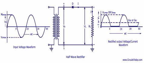
TransistorThe Construction of a PNP TransistorDescribe the construction of a PNP transistorA transistor is a semiconductor device used to amplify and switch electronic signals and electrical power.It is composed of semiconductor material with at least three terminals for connection to an external circuit.The Mode of Action of a PNP TransistorExplain the mode of action of a PNP transistorThe transistor is the fundamental building block of modern electronic devices, and is ubiquitous in modern electronic systems.A voltage or current applied to one pair of the transistor's terminals changes the current through another pair of terminals. Because the controlled (output) power can be higher than the controlling (input) power, a transistor can amplify a signal.The Types of TransistorsIdentify the types of transistorsThere are two types of transistors, which have slight differences in how they are used in a circuit:- Bipolar transistor
- Field-effect transistor
Bipolar transistorA bipolar transistor has three terminals labeled base, collector, and emitter. A small current at the base terminal (that is, flowing between the base and the emitter) can control or switch a much larger current between the collector and emitter terminals. There are two types of bipolar transistors:- n-p-n transistors
- p-n-p transistors
Field-effect transistorFor a field-effect transistor, the terminals are labeled gate, source, and drain, and a voltage at the gate can control a current between source and drain.N-P-N transistor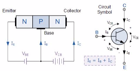 (Note: Arrow defines the emitter and conventional current flow, “out” for a Bipolar NPN Transistor).The construction and terminal voltages for a Bipolar NPN Transistor are shown above. The voltage between the Base and Emitter ( VBE ), is positive at the Base and negative at the Emitter because for an NPN transistor, the Base terminal is always positive with respect to the Emitter. Also the Collector supply voltage is positive with respect to the Emitter ( VCE ). So for a bipolar NPN transistor to conduct the Collector is always more positive with respect to both the Base and the Emitter.
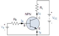
NPN Transistor ConnectionThen the voltage sources are connected to an NPN transistor as shown. The Collector is connected to the supply voltage VCC via the load resistor, RL which also acts to limit the maximum current flowing through the device. The Base supply voltage VB is connected to the Base resistor RB, which again is used to limit the maximum Base current.So in a NPN Transistor it is the movement of negative current carriers (electrons) through the Base region that constitutes transistor action, since these mobile electrons provide the link between the Collector and Emitter circuits. This link between the input and output circuits is the main feature of transistor action because the transistors amplifying properties come from the consequent control which the Base exerts upon the Collector to Emitter current.Then we can see that the transistor is a current operated device (Beta model) and that a large current ( Ic ) flows freely through the device between the collector and the emitter terminals when the transistor is switched “fully-ON”. However, this only happens when a small biasing current ( Ib ) is flowing into the base terminal of the transistor at the same time thus allowing the Base to act as a sort of current control input.The transistor current in a bipolar NPN transistor is the ratio of these two currents ( Ic/Ib ), called the DC Current Gain of the device and is given the symbol of hfe or nowadays Beta, ( β ). The value of β can be large up to 200 for standard transistors, and it is this large ratio between Ic and Ib that makes the bipolar NPN transistor a useful amplifying device when used in its active region as Ib provides the input and Ic provides the output. Note that Beta has no units as it is a ratio.Also, the current gain of the transistor from the Collector terminal to the Emitter terminal, Ic/Ie, is called Alpha, ( α ), and is a function of the transistor itself (electrons diffusing across the junction). As the emitter current Ie is the sum of a very small base current plus a very large collector current, the value of alpha α, is very close to unity, and for a typical low-power signal transistor this value ranges from about 0.950 to 0.999.α and β Relationship in a NPN Transistor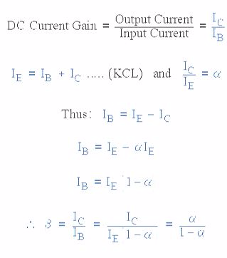 By combining the two parameters α and β we can produce two mathematical expressions that gives the relationship between the different currents flowing in the transistor.
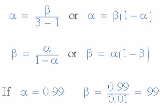 The values of Beta vary from about 20 for high current power transistors to well over 1000 for high frequency low power type bipolar transistors. The value of Beta for most standard NPN transistors can be found in the manufactures data sheets but generally range between 50 – 200.The equation above for Beta can also be re-arranged to make Ic as the subject, and with a zero base current ( Ib = 0 ) the resultant collector current Ic will also be zero, ( β x 0 ). Also when the base current is high the corresponding collector current will also be high resulting in the base current controlling the collector current. One of the most important properties of the Bipolar Junction Transistor is that a small base current can control a much larger collector current. Consider the following example.P-N-P transistorThe PNP Transistor is the exact opposite to the NPN Transistor device we looked at in the previous tutorial. Basically, in this type of transistor construction the two diodes are reversed with respect to the NPN type giving a Positive-Negative-Positive type of configuration, with the arrow which also defines the Emitter terminal this time pointing inwards in the transistor symbol.Also, all the polarities for a PNP transistor are reversed which means that it “sinks” current into its Base as opposed to the NPN Transistor which “sources” current through its Base. The main difference between the two types of transistors is that holes are the more important carriers for PNP transistors, whereas electrons are the important carriers for NPN transistors.Then, PNP transistors use a small base current and a negative base voltage to control a much larger emitter-collector current. In other words for a PNP transistor, the Emitter is more positive with respect to the Base and also with respect to the Collector.The construction of a “PNP transistor” consists of two P-type semiconductor materials either side of an N-type material as shown below.
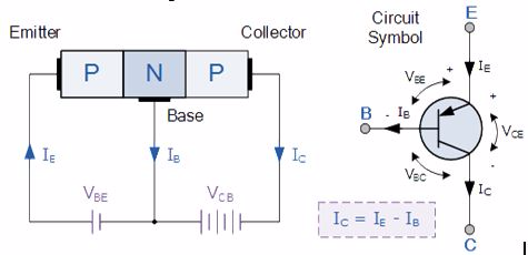 (Note: Arrow defines the emitter and conventional current flow, “in” for a PNP transistor).The construction and terminal voltages for an NPN transistor are shown above. The PNP Transistor has very similar characteristics to their NPN bipolar cousins, except that the polarities (or biasing) of the current and voltage directions are reversed for any one of the possible three configurations looked at in the first tutorial, Common Base, Common Emitter and Common Collector.
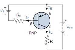 PNP Transistor ConnectionThe voltage between the Base and Emitter ( VBE ), is now negative at the Base and positive at the Emitter because for a PNP transistor, the Base terminal is always biased negative with respect to the Emitter.Also the Emitter supply voltage is positive with respect to the Collector ( VCE ). So for a PNP transistor to conduct the Emitter is always more positive with respect to both the Base and the Collector.The voltage sources are connected to a PNP transistor are as shown. This time the Emitter is connected to the supply voltage VCC with the load resistor, RL which limits the maximum current flowing through the device connected to the Collector terminal. The Base voltage VB which is biased negative with respect to the Emitter and is connected to the Base resistor RB, which again is used to limit the maximum Base current.To cause the Base current to flow in a PNP transistor the Base needs to be more negative than the Emitter (current must leave the base) by approx. 0.7 volts for a silicon device or 0.3 volts for a germanium device with the formulas used to calculate the Base resistor, Base current or Collector current are the same as those used for an equivalent NPN transistor and is given as.
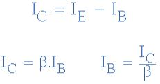 We can see that the fundamental differences between a NPN Transistor and a PNP Transistor is the proper biasing of the transistors junctions as the current directions and voltage polarities are always opposite to each other. So for the circuit above: Ic = Ie – Ib as current must leave the Base.Generally, the PNP transistor can replace NPN transistors in most electronic circuits, the only difference is the polarities of the voltages, and the directions of the current flow. PNP transistors can also be used as switching devices and an example of a PNP transistor switch is shown below.
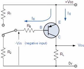 The Output Characteristics Curves for a PNP transistor look very similar to those for an equivalent NPN transistor except that they are rotated by 180o to take account of the reverse polarity voltages and currents, (the currents flowing out of the Base and Collector in a PNP transistor are negative). The same dynamic load line can be drawn onto the I-V curves to find the PNP transistors operating points.The Application of Transistors in Daily LifeOutline the applications of transistors in daily lifeTransistors are used in all electronic devices such as calculators, tv, radios, computers etc.They are used in switching circuits, amplifier circuits, oscillator circuits, current source circuits, voltage regulator circuits, power supply circuits, digital logic intergrated circuits and in any circuit that uses small control signals to control larger currents.6: ELEMENTARY ASTRONOMY
Single Stage AmplifierThe Concept of Analogue SignalsExplain the concept of analogue signalsAn Analog signal is any continuous signal for which the time varying feature (variable) of the signal is a representation of some other time varying quantity, i.e., analogous to another time varying signal. It differs from a digital signal in terms of small fluctuations in the signal which are meaningful.The Concept of Digital SignalExplain the concept of digital signalA digital signal uses discrete (discontinuous) values. By contrast, non-digital (or analog) systems use a continuous range of values to represent information. Although digital representations are discrete, the information represented can be either discrete, such as numbers or letters, or continuous, such as sounds, images, and other measurements of continuous systems.Properties of Digital vs Analog signalsDigital information has certain properties that distinguish it from analog communication methods. These include:- Synchronisation – digital communication uses specific synchronisation sequences for determining synchronisation.
- Language – digital communications requires a language which should be possessed by both sender and receiver and should specify meaning of symbol sequences.
- Errors – disturbances in analog communication causes errors in actual intended communication but disturbances in digital communication does not cause errors enabling error free communication. Errors should be able to substitute, insert or delete symbols to be expressed.
- Copying – analog communication copies are quality wise not as good as their originals while due to error free digital communication, copies can be made indefinitely.
- Granularity – for a continuously variable analog value to be represented in digital form there occur quantization error which is difference in actual analog value and digital representation and this property of digital communication is known as granularity.
Differences in Usage in EquipmentMany devices come with built in translation facilities from analog to digital. Microphones and speaker are perfect examples of analog devices. Analog technology is cheaper but there is a limitation of size of data that can be transmitted at a given time.Digital technology has revolutionized the way most of the equipments work. Data is converted into binary code and then reassembled back into original form at reception point. Since these can be easily manipulated, it offers a wider range of options. Digital equipment is more expensive than analog equipment.Comparison of Analog vs Digital Quality:Digital devices translate and reassemble data and in the process are more prone to loss of quality as compared to analog devices. Computer advancement has enabled use of error detection and error correction techniques to remove disturbances artificially from digital signals and improve qualityDifferences in Applications:Digital technology has been most efficient in cellular phone industry. Analog phones have become redundant even though sound clarity and quality was good.Analog technology comprises of natural signals like human speech. With digital technology this human speech can be saved and stored in a computer. Thus digital technology opens up the horizon for endless possible uses.A Single-Stage AmplifierDesign a single-stage amplifierSingle-stage amplifierhave only one amplifying device. It consists of amplification stage that includes a transistor. The transistor is connected to a load resistor through which a load current flows. The value of the load resistor together with the transconductance value affects the amplifier’s voltage gain.Single-stage amplifiers include:- Common-emitter (CE) amplifier
- Common-collector (CC) amplifier
- Common-base (CB) amplifier
It is called the common-emitter configuration because (ignoring the power supply battery) both the signal source and the load share the emitter lead as a common connection pointCommon-emitter amplifierIt is called the common-emitter configuration because (ignoring the power supply battery) both the signal source and the load share the emitter lead as a common connection point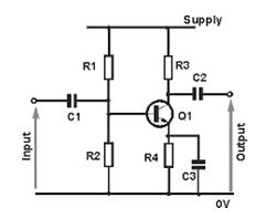
Common-emitter amplifier: The input and output signals both share a connection to the emitterBefore, a small solar cell current saturated a transistor, illuminating a lamp. Knowing now that transistors are able to “throttle” their collector currents according to the amount of base current supplied by an input signal source, we should see that the brightness of the lamp in this circuit is controllable by the solar cell’s light exposure. When there is just a little light shone on the solar cell, the lamp will glow dimly. The lamp’s brightness will steadily increase as more light falls on the solar cell.Common collector amplifierIt is called the common-collectorconfiguration because (ignoring the power supply battery) both the signal source and the load share the collector lead as a common connection point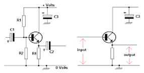
Common collector: Input is applied to base and collector. Output is from emitter-collector circuit.It should be apparent that the load resistor in the common-collector amplifier circuit receives both the base and collector currents, being placed in series with the emitter. Since the emitter lead of a transistor is the one handling the most current (the sum of base and collector currents, since base and collector currents always mesh together to form the emitter current), it would be reasonable to presume that this amplifier will have a very large current gain. This presumption is indeed correct: the current gain for a common-collector amplifier is quite large, larger than any other transistor amplifier configuration. However, this is not necessarily what sets it apart from other amplifier designs.Common-base amplifierIt is called the common-base configuration because (DC power source aside), the signal source and the load share the base of the transistor as a common connection point shown in.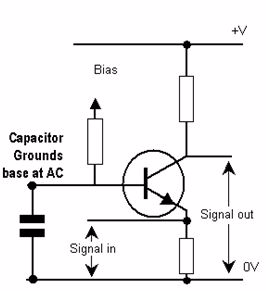
Common-base amplifier: Input between emitter and base, output between collector and base.Perhaps the most striking characteristic of this configuration is that the input signal source must carry the full emitter current of the transistor, as indicated by the heavy arrows in the first illustration. As we know, the emitter current is greater than any other current in the transistor, being the sum of base and collector currents. In the last two amplifier configurations, the signal source was connected to the base lead of the transistor, thus handling the least current possible.Because the input current exceeds all other currents in the circuit, including the output current, the current gain of this amplifier is actually less than 1 (notice how Rload is connected to the collector, thus carrying slightly less current than the signal source). In other words, it attenuates current rather than amplifying it. With common-emitter and common-collector amplifier configurations, the transistor parameter most closely associated with gain was β. In the common-base circuit, we follow another basic transistor parameter: the ratio between collector current and emitter current, which is a fraction always less than 1. This fractional value for any transistor is called the alpharatio, or α ratio. - Introduction to AstronomyThe Concept of AstronomyExplain the concept of astronomyAstronomy is a branch of science which deals with the study of origin,evolution, composition, distance and the motion of all bodies and scattered matter in the universe.
- Universe is the totality of space and time together with matter and energy.
- Astronomers are the people who deals astronomy.
The Importance of Astronomy in Everyday LifeExplain the importance of astronomy in everyday lifeImportance of astronomy include:- It was the earliest method of measuring time.
- It was used to develop calendars that made it possible to predict the seasons.
- It is used in navigation.-Helps us to understand the earth and the life it supports originated from and how it evolved.
- It presents a new frontier for exploration.
Solar SystemDifference between a Star and a PlanetDistinguish between a star and a planetThe solar system is made up of the sun and the celestial objects bound to it by gravity.These objects include the eight planets and their known moons and billions of small bodies that include asteroids,comets,meteoroids and interplanetary dust.Stars and planetsA star is a large celestial body made up of hot gases known as plasma.Plasma is an ionized gas in which a certain proportion of electrons are free rather than bound to an atom or molecule.The sun is a large star. The sun is also the closest star to the earth. Astronomical unit is the distance between the earth and the sun which is used to measure distances across the solar system (its value is approximately 149.60 million kilometers).A Galaxy is a giant collection of stars,gas and dust.Most stars in the universe are in the galaxies. Nearly all of the stars visible in the night sky are within our own galaxy, sometimes called the Milky Way Galaxy.Planet is a major (large) object which is in orbit around a star.There are eight planets which are Mercury, Venus, Earth, Mars, Jupiter, Saturn, Uranus, and Neptune.Characteristics of a planet- It is a celestial body that orbits a star.
- It is massive enough so that its own gravity cause it to assume a spherical shape.
- It has cleared the neighbourhood around its orbit.
Pluto is not considered as a planet because it resides in an area of space populated by numerous other objects.It is now designated a dwarf planet.The dwarf planet does not meet the third characteristic i.e has not cleared the neighbourhood around its orbit.Differences between stars and planetsStars Planets Emit their own light Do not emit their own light Twinkle at night Do not twinkle at night Appear to be moving from east to west. Planets move around the sun from west to east. Their temperatures are usually very high Their temperature depends on their distances from the sun Countless in number There are eight in the solar system Very big in size but they appear small because they are very far away Very small in size as compared to stars. Asteroids (minor planets) are small solar system bodies in orbit around the sun,especially in the inner solar system.Asteroids are smaller than planets but larger than a speck of dust.A comet is a solid body orbiting the sun typically composed of rock dust or ice. Most comets were formed from condensed interstellar gas and dust clouds in the early stages of the creation of the universe.The Force of Gravitation which Maintains Celestial Bodies in their OrbitsExplain the force of gravitation which maintains celestial bodies in their OrbitsGravitation force is the attractive force existing between any two objects that have mass. It pulls objects together and acts on all matter on the universe, hence it is sometimes referred to as universal gravitation.Newton’s law of universal gravitationIt states that: ‘Every single point mass attracts every other point by a force directed along the line joining the two masses.'The force is proportional to the product of the two masses and inversely proportional to the square of the distance between the point masses. Where:
- F is the magnitude of the attractive force between the two point masses.
- G is the universal gravitation constant.m₁ is the mass of the first point mass.
- m₂ is the mass of the second point mass.
- r is the distance between the centers of the two point masses.
Gravitation force is actually very weak force.The huge gravitational force of the nearest star,the sun,holds together the eight planets of the solar system. The planets move round the space at speeds that just balance the sun’s gravitational pull, so they are locked into a permanent path (orbit) around the sun.Natural satellites (moons) orbits planets while artificial satellites orbit the earth in the same way as the moon orbits the planets.Gravity is the gravitational force that occurs between the earth and the other objects.It pulls the objects towards the center of the earth.It holds us on the ground and causes objects to fall back to the ground after being thrown uo in the air.The earth gravitational pull extends out into space in all directions. The further you move away from the center of the earth,the weaker the force becomes. The measure of the force of gravity on an object on the earth’s surface is the weight of that object and is measured in newton (N).The weight of an object changes depending on its location in the universe.
ConstellationsThe Concept of ConstellationExplain the concept of constellationConstellation is a group of stars that form a definite shape or pattern when viewed from the earth.Constellations are usually named after mythological characters, people, animals and things. There are about 88 known constellations. The various constellations are visible during a particular period of the year.The ConstellationIdentify constellationActivity 1In a group of five, draw any five constellations on a Manila paper.The Uses of Constellation in Everyday LifeUses of constellation in everyday lifeUse of knowledge about constellations include:- Religious-In early days, people thought that the gods lived in the heavens and that the gods created the constellations. Many cultures believed that the position of the stars were their god’s way of telling stories.
- Agricultural.-Before there were proper calendars, people had no way of determining when to sow or harvest except by the stars. Constellations made the patterns of the stars easy to remember
- Navigation. One can figure out his or her latitude (North or South) just by looking how high Polaris (The North Star) appear in the night sky. This allowed the ships to travel across the globe.
The Earth and the MoonThe Surface Features and Temperature of the MoonDescribe the surface features and temperature of the moonThe moon of the earth is the sixth largest in the solar system. It has a diameter of 3,476km and a mass of 7.35 x 10²²kg. Like the earth, the moon has an iron core surrounded by a rocky mantle and crust.Unlike the earth, no part of the moon’s iron core is molten so it does not have a magnetic field.Surface gravity on the moon is 1/6 that of the earth.The moon revolves in a anticlockwise direction around the earth in an elliptical orbit. The moon’s orbit is tilted at 5° relative to the earth’s orbit around the sun.The distance between the earth and the moon varies from perigee (nearest the earth) where it is 356,000km to apogee (furthest from the earth) where it is 406,000km. The average distance is 384,000km.It take the moon 27.3 earth days to complete one orbit, a period of time called the Sidereal month.The moon also rotates about its axis at a rate equal to its rate of revolution. The result of this is that one side of the moon face the earth. The side which faces the earth is called the near side while the side which faces away is called the far side.The spinning of the earth causes the moon to rise and set each day ,just like the sun. However, because of moons’ orbital motion around the earth ,it(the moon) rises about 50 minutes later each day .As a result, the moon can be seen at different times of the day and night during a month.The temperatures on the surface of the moon are on average 107°C during the day and 53°C during the night.Surface features of the moon.There are two primary types of terrain on the moon. These are;- Heavily cratered very old lunar highlands.
- Relatively smooth and younger Maria.
From the surface of the earth,the moon’s surface appears to have bright and dark regions when viewed with the unaided eye.The bright areas are the lunar highlands that have many craters and covered with a highly reflective layer of fine dust. The highlands are geologically the oldest parts of the moon’s surface.The dark areas are low areas similar to ocean basins on the earth. They are with dark solidified lava and are less cratered than the highlands. Galileo called these areas matia, Italian word for seas, because their dark smooth surface appears to be large bodies of water.The maria which makes 16% of the moon’s surface , are huge impact craters that were later flooded with molten lava. Most of the maria is covered with regolith,a mixture of fine dust and rocky debris produced by meteor impact.The Causes of Ocean TidesExplain the causes of ocean tidesTides are periodic rises and falls of large bodies of water caused mainly by gravitational interaction between the earth and the moon.The earth and the moon are attracted each other, just like magnets are attracted to each other. The moon rises to pull at anything on the earth to bring it closer. But the earth is able to hold onto everything except the water. Since the water always moving, the earth can't hold onto it and the moon is able to pull at it. This results into ocean tides.Each day, there are two high tides and two low tides. The ocean constantly moves from high tide to low tide, and then back to high tide. There is a time interval of about 12 hours and 25 minutes between the two high tides.How tides occurGravitational attraction of the moon causes the oceans to bulge out in the direction of the moon. Another bulge occurs on the opposite side since the earth is also being pulled towards the moon (and away from the water on the far side).Ocean levels fluctuate daily as the sun, moon and earth interact .As the moon travels around the earth, and as they together travel around the sun, the combined gravitational forces cause the world ocean water levels to rise and fall. Since the earth is rotating while this is happening, two tides occur each day.Types of tidesThere are two types of tides:Spring tidesThey occur during the full moon and the new moon. During this time, the earth,the sun and the moon are in a line. The gravitational forces of the moon and the sun both contribute to the tides.At these times, the high tides are very high and the low tides are very low. These are known as spring high tines and spring low tides respectively.Spring tides are especially strong tides.Proxigen spring tide is a rare unusually high tide. It occurs when the moon is both unusually close to the earth (at its closest perigee, called the proxigee) and in the new moon phase(when the moon is between the earth and the sun).The proxigen spring spring tide occurs at most once every 1.5 years.Neap tideWhen the sun and the moon are not aligned, the gravitational forces cancel each other out, and the tides are not very high or very low. These are called neap tides.They occur during quarter moons. During this time, the gravitational forces of the moon and the sun are perpendicular to one another (with respect to the earth).This causes the bulges to cancel each other. The result is a smaller difference between high and low tide and is known as a neap tide. Neap tides are especially weak tides.
TOPIC 7: GEOPHYSICSGeophysics is a branch of science that deals with the physical, chemical, geological, astronomical and other characteristic properties of the earth.It deals with geological phenomena such as the temperature distribution of the earth’s interior, the source, configuration and the geomagnetic field.
Structure and Composition of the EarthThe Structure of the EarthDescribe the structure of the earthThe structure of the earth is composed of three major zones arranged in concentric manner. These are crust, mantle and core.The crustIs the outer solid layer o the earth.It is extremely thin(5 to 15km) compared to the radius of the earth (6,371km).There are two types of crust, namely:- Continental crust: This is heterogeneous and of relatively low density(2 to 2.8 tonnes per cubic meter).-It is composed mainly of granites and sedimentary rocks.
- Oceanic crust: This is basaltic and more denser (3.0 to 3.1 tonnes per cubic meter). Both the continental and the oceanic crusts floats on the denser mantle. Because of its low density,the continental crust floats on the mantle at a higher elevation, forming the land masses and mountains. The continental crust is 30 to 70 km thick. The denser oceanic crust floats at a lower elevation forming oceanic basins.It is about 8km thick. The boundary between the crust and the mantle is called Mohorocivic discontinuity or simply Moho. It is a zone between one and several kilometers thick.
The mantleIt begins from the Moho and extends to a depth of 2,900km below the earth’s surface,up to its boundary with the earth’s core.This boundary is called the Gutenberg discontinuity.The mantle contains about 70% of the earth’s mass.It is composed of rocks,both in solid and mountain states.The upper surface of the mantle has the temperature of about 870°C,and this temperature increases downwards through the mantle to about 2,200°C near the core.The coreIs the innermost part of the earth.It extends from the Gutenberg discontinuity to the earth’s geometric centre. The core consists of two distinct regions namely:- The inner core: It is composed of solid material because the high pressure at this depth.-It is composed of iron-nickel alloys.
- The outer core: Is composed of liquid of molten nickel and iron known as magma. It extends from the mantle to a depth of about 5,000km below the earth’s surface.
Activity 1In groups of five, discuss why the outer core is liquid while the inner core is solid.The Composition of the Layers of the EarthDescribe the composition of the layers of the earthContinental crust is made of granite and sedimentary rocks forming the lands and the mountains while the oceanic crust forms oceanic basins. Mantle is made of solids and molten rocks. The outer core is made of molten nickel and iron called magma while the inner core is solid because of the high pressure. The crust and the mantle are separated by the mohorovicic discontinuity.The Importance of the Layers of the EarthExplain the importance of the layers of the earthContinental crust forms the land and mountains of the earth on which all human activities are carried out e.g farming, housing etc. Oceanic crust forms the base of the oceans and seas on which oceanic water rests and all aquatic organisms like fishes live. The mantle provides the heat transfer from the core to the outer layers a process which causes the volcanic actions and earthquakes.
Earthquake and VolcanoesBoth of them, volcano and earthquake are caused by the movement of molten rock and heat deep inside the earth. These movements are referred to as subterranean movements. Most earthquakes and volcanic activity happen near tectonic boundaries.The Origin of VolcanoesExplain the origin of volcanoesVolcanoes are places where molten rock called magma leaks out through a hole or a crack in the earth’s crust.Magma originates from the mantle,where high temperature and pressure cause the rock to melt.When a large pool of magma if formed,it rises through the denser rock layer towards the earth’s surface.Magma that has reached the earth’s surface is called lava. Most volcanoes form along constructive and destructive boundaries between tectonic plates.However a few form plate boundaries.Types of volcanoesThere are two main types of volcanoes, namely:- Fissure volcanoes: These occur along the cracks in and between tectonic plates. They can be many kilometers long. Lava is usually ejected quietly and continuously,forming enormous plains or plateaus of basaltic volcanic rock.
- Central volcanoes: These have a single vertical main vent through which mzgm reaches the earth’s surface. They usually develop a cone shape that builds up from successive layers of lava and ash.
Classification of volcanoesVolcanoes are classified into three categories based on their frequency of eruption, namely:- Active volcanoes: Are those that either erupt constantly or have erupted in recent times. Eg; Oldonyo Lengai.
- Dormant volcanoes: Are those that have been inactive for some time(a few thousand years) but can erupt again. Eg; Mt Kilimanjaroc.
- Extinct volcanoes: They have not erupted in recorded history. They will probably never erupt again.
Effects of VolcanoesDescribe effects of volcanoesEffects of volcanoes include:- Landscape: Most of the earth’s surface is covered with volcanic rocks.Volcanoes are also responsible for the formation of many mountains and islands.
- Vegetation and wildlife: Volcanic eruption sometimes set the surrounding vegetation into fire.Wild animals are also killed by being buried into the lava or being burnt by the forest fires.
- Environment: Volcanic eruptions emit harmful gases into the environment. Such gases include sulphur dioxide. Some of the gases contribute to global warming and climate change.
- Human life and property: Volcanic eruptions sometimes kill people and destroy property.
- Soil: Volcanoes help in soil formation by bringing important minerals from from deep underground onto the earth’s surface.
- Minerals: Volcanoes also bring valuable minerals to the earth’s surface.The minerals are important economic resources.
The Origin of EarthquakeExplain the origin of earthquakeAn earthquake is a sudden motion or shaking of the earth caused by a sudden relese of energy that has accumulated within or along the edges of the earth’s tectonic plates.Earthquakes happen when rocks in the earth’s crust move suddenly, shaking the earth.Earthquake also occur as a result of movement of magma at constructive boundaries under volcanoes and where continental plates collide and push mountain ranges.How earthquake occurEarthquakes mostly occur on or near the boundaries between tectonic plates.However ,earthquakes can also occur far from plate boundaries. Such earthquakes probably occur as a result of faults formed millions of years ago.Pressure liquid builds between them until the friction force holding the plates together gives way.The plates move suddenly,releasing the pressure or energy and then holds together again. This sudden jerk is what is felt as an earthquake.The point within the earth where an earthquake begins is called the hypocenteror the focus of the earthquake. Earthquake rarely occur along constructive plate boundaries.Seismic wavesThis refers to the energy released by an earthquake. They are grouped into three categories:- Primary waves or p-waves: Are the first waves released from the hypocenter. They are felt as a sudden jolt.
- Secondary waves or s-waves: These arrive a few soconds later after p-waves.They are felt as a series of side-to-side tremors.
- Surface waves.-They radiate outward from the point on the earth’s surface directly above the hypocentre. This point is called the epicentre of the earthquake.
There are two types of surface waves:- Reyleigh waves- create a rolling movement that makes the land surface move up and down.
- Love waves- make the ground shift from side to side. It is the surface waves that demage to surface structure such as buildings and hydroelectric power plants.
The Principle of MeasurementDescribe the principle of measurement of earthquakeThe nature of an earthquake is usually described by measuring two properties, namely the magnitude and intensity.The magnitude of an earthquake is a measure of the energy it releases. It is usually measured on the Richter scale.The Richter scale magnitudes are based on a logarithmic scale(base 10).The intensity of an earthquake is a measure of its strength based on the changes it causes to the landscape.The intensity is usually measured on the Modified Mercalli scale.The scale is calibrated 1 to 12.Note:An earthquake can have only one magnitude. However its intensity reduces as the seismic waves spread out from the hypocentre,just the same way the loudness of a sound changes as you move away from the source.The Seismograph:Is an instrument used to record ground movements caused by earthquakes. It measures ground oscillations by recording the relative motion between a pendulum and the ground. It is also possible to use the ratio between the deflection and the of the pendulum and the acceleration of the of the ground to record an earthquake.Precaution against Earthquake HazardsIdentify precaution against earthquake hazardsEarthquakes hazardsThe following are some of the hazards associated with earthquakes:- Landslides
- Tsunamis
- Collapsing buildings
- Fire outbreak
- Backward rivers
Earthquake warning signsThe following are important signs that are observed before an earthquake occurs:- Thermal indicator
- Water indicator
- Seismo electromagnetic indicator
- Animal indicator
- Human indicator
Precautions to be taken during an earthquakeThe following are some precautions that can be taken to minimise injuries or death of human beings in the event of an earthquake:- If you are indoors during an earthquake ,drop,cover and hold on.Get under a desk,table or a bench.Hold on to one of the legs and cover your eyes.If there is no desk or table nearby, sit down against an interior wall.
- Pick a safe place where things will not fall on you-away from windows or tall heavy furniture.
- Do not run outside when the earthquake happens because bricks, roofing and other materials may fall from buildings during and immediately after an earthquake, injuring persons near the building.
- Wait in your safe place until the shaking stops, then check to see if you are hurt. You will be better able to help others if you take care of yourself first,then check on the people around you.
- Move carefully and watch out for things that have fallen or broken creating hazards. Be ready for additional earthquakes called after shocks.
- Be on the lookout for fires. Fire is the most common earthquake-related hazard due to damaged gas and electrical lines.
- If you must leave a building after the shaking stops, use the stairs and not elevator. Earthquakes can cause fire alarms and fire sprinklers to go off. You will not be certain whether there is a real threat of fire. As a precaution,use the stairs.
- If you are outside during an earthquake,stay outside. Move away from buildings, trees, streetlights and power lines. Crouch down and cover your head. Bricks,roofing and other materials can fall from buildings, injuring persons nearby.Trees, streetlights and poor lines may also fall, causing damage or injury.
Structure and Composition of the AtmosphereThe Vertical Structure of the AtmosphereDescribe the vertical structure of the atmosphereThe atmosphere is a layer of gases containing numerous small suspended solid and liquid particles surrounding the earth.It has no outer boundary,it just fades into space.The dense part of the atmosphere lies within 30km above the earth’s surface.The atmosphere is divided into regions based on its thermal characterestics (temperature changes),chemical composition, movement and density. It is divided into five regions, which are:- Troposphere
- Stratosphere
- Mesosphere
- Thermosphere
- Exosphere
The Composition of the AtmosphereDescribe the composition of the atmosphereTroposphereThis is the region nearest to the earth’s surface which extends to an altitude up to 10 km above the poles and 20km above the equator.It is the most dense part of the atmosphere(80% by mass of the atmosphere) which contains most of the atmosphere's water vapour.The temperature in this region decreases with altitude at an average rate of 6°C/km.It encourages the change of weather(most of weather phenomenon occur in the troposphere).Clouds and rain are formed within this region.The boundary which separates the tropospher from the the stratosphere is called the tropopause. At the tropopause,the temperature stop decreasing with altitude and becomes constant. The tropopause has an average height of about 10km.StratosphereIt starts from the tropopause and extends to 50km high.It is more stable,drier and less dense compared to troposphere.The temperature slowly increases with altitude due to the presence of ozone layer which absorbs ultraviolet rays from the sun. The ozone layer lies in the middle of the stratosphere between 20 and 30km. Ozone is triatomic(three-molecules) form of oxygen.The stratosphere together with with troposphere are collectively known as the lower atmosphere.The boundary which separates the stratosphere from the outer layer is called the stratopause.Advantages of stratosphereIt absorbs the ultraviolet radiations which would otherwise reach the earth’s surface which is harmful to both plants and animals.It prevents large storms from extending much beyond the troposphere due to its stability. Planes also fly within this layer because it has strong steady horizontal winds which are above the stormy weather of the troposphere.MesosphereIt starts just above the stratosphere and extends to 85km high.The temperature at this layer decreases with altitude.The lowest temperature of the atmosphere occurs within this region(-90°C).Is the layer where most meteors burn while entering the earth’s atmosphere.The boundary which separates the mesosphere from the thermosphere is called the mesopause.ThermosphereIt is just above the mesopause and extends up to 690km high. The temperature increases with altitude due to the sun’s heat.The temperature in this region can go as high as1727°C and chemical reactions occur faster in this region than on the earth’s surface.This layer is also known as the upper atmosphere. The lower part of the thermosphere,from 80 to 550km above the earth’s surface, contains the ionosphere. This is a region containing a high concentration of charged particles called ions and free electrons.Importance of ionosphereThe large number of free electrons in the ionosphere allows the propagation of electromagnetic waves. It absorbs the dangerous radiations like X-rays and extreme ultraviolet(EUV) radiation. It plays an important role in communition of radio waves.ExosphereIs the outermost region of the atmosphere.In this region,the atmospheric gas pressure is very low such that light atoms such as hydrogen and helium may acquire sufficient energy to escape the earth’s gravitational pull.The upper part of the exosphere is called magnetosphere.The motion of ions in this region is strongly constrained by the presence of the earth’s magnetic field.This is the region where satellites orbit the earth.The Importance of Various Layers of the AtmosphereExplain the importance of various layers of the atmosphereThe importance of the atmosphere include the following:- The troposphere controls the climate and ultimately determines the quality of life on the earth.
- The troposphere is important for life on earth. The layer contains gases which include oxygen which is used for respiration by animals and carbon dioxide which is used by plants in photosynthesis. The nitrogen found in this laye also provides an inactive environment for many chemical processes to take place. The gases also support many important chemical processes such as combustion,weathering and oxidation.
- The stratosphere prevents harmful ultraviolet radiation from reaching the earth.
- The mesosphere,thermosphere and exosphere also prevent harmful radiation such as cosmic rays from reaching the earth’s surface.
- Communication is also made possible by some layers of the atmosphere, specifically the ionosphere.
The Greenhouse Effect and Global Warming
The Greenhouse EffectExplain the greenhouse effectGlobal warming is the increase of the average temeratures near or on the surface of the earth as a result of what is known as the greenhouse effect. The effect is caused by greenhouse effect. These gases are produced from natural and industrial processes.The greenhouse effect is the process in which the emission of radiation by the atmosphere warms the earth’s surface.When heat from the sun reaches the earth’s surface in form of sunlight,some of it is absorbed by the earth.The rest is radiated back to the atmosphere at a longer wavelength than the incoming sunlight.Some of these longer wavelengths are absorbed by greenhouse gases in the atmosphere before they are lost to space.The absorption of this long-wave radiant energy warms the atmosphere.The greenhouse gases act like a mirror, reflecting back to the earth some of the heat energy which would otherwise be lost to space.
Sources of Greenhouse EffectIdentify sources of greenhouseSources of greenhouse effect include:- Carbondioxide
- Clearing and burning of vegetation
- Burning of fossil fuel
- Methane
- Dinitrogen oxide
- Chlorofluorocarbons(CFCs)
The Occurence of Global WarmingExplain the occurrence of global warmingGlobal warming is primarily a problem of too much carbon dioxide (CO2) in the atmosphere—which acts as a blanket, trapping heat and warming the planet. As we burn fossil fuels like coal, oil and natural gas for energy or cut down and burn forests to create pastures and plantations, carbon accumulates and overloads our atmosphere. Certain waste management and agricultural practices aggravate the problem by releasing other potent global warming gases, such as methane and nitrous oxide.The Consequences of Global WarmingState the consequences of global warmingEffects of Global Warming- Increase in the temperature of the oceans.
- Rise in sea levels.
- Change in world’s climatic pattern.
- Acidification of the oceans.
- Extreme weather events.
- Higher or lower agricultural yields.
- Melting of Arctic ice and snowcaps. This cause landslides, flash floods and glacial lake overflow.
- Extinction of some animal and plant species.
- Increase in the range of disease vectors, that is,organisms that transmit diseases.


No comments